# Soundec Studio User Manual
# Overview
Soundec Studio graphics development tool is a software specifically designed for the development and tuning of Soundec professional audio processors. It can directly import application routines and parameters for setting and adjusting parameters. Using this tool, engineers without experience in writing DSP code can easily implement DSP in their designs.
Soundec Studio can be connected with Soundec Playground Evaluation Board(EVB) to provide complete online real-time application control. Soundec Studio not only provides basic underlying DSP functions and control modules, but also includes a rich library of algorithms, capable of performing audio processing functions such as filtering, equalizer, and dynamic processing. The standard library includes advanced recording-end processing algorithms such as enhanced stereo acquisition and wind noise detection.
Soundec Studio can setup control registers and execute functions in a visual way. In addition to graphical DSP signal flow development, Soundec Studio also has other features that can shorten the product design cycle from concept to release.
# Installation
Please download Soundec Studio.zip at the end of this document. Uncompress downloaded zip file and run SoundecStudio.exe.
# Start, Connect with Soundec Evaluation Board
Open Soundec Studio and connect with Soundec Evaluation Board. Following is the start screen:
After successful connection, the main interface is shown in the following figure:
# Profile
Soundec Studio uses .flex files as parameter configuration record files. User can click on the File menu in Soundec Studio and then find the corresponding sub-menu to proceed with the next step, or use the corresponding shortcut.
# Import Profile from Device
Please click "File"->"Import Profile from Device" after opening Soundec Studio and connecting EVB successfully. It may take several seconds to read parameters from EVB. After clicking OK, the evaluation board data will be read and displayed in Soundec Studio.
The following is Soundec Studio screen snapshot after imported profile from evaluation board:
# Save Profile
"Save Profile" will save displayed parameters to local file with extension name of flex.
# Save As
"Save As" will save displayed parameters to a .flex file with specified file name.
# Open Profile
If there is a corresponding .flex file in local disk of computer, after connecting to the evaluation board in Soundec Studio, click the button Open Profile menu to open the local .flex file and read the configuration data in flex file.Then, the system(Soundec Studio) will synchronize data to the device's(evaluation board) RAM. After data synchronization is completed, it will be displayed in the Soundec Studio interface.
# Device
The Device menu includes evaluation board RAM and Flash operations .
# Sync to RAM
Please click on "Device" -> "Sync to RAM" sub-menu in Soundec Studio."Sync to RAM" will sync all displayed parameters to device and update register values. Please note that updated register value will not be saved to device flash automatically. EVB will set to default value saved in flash after reboot.
# Burn to Flash
Please click on the"Device" -> "Burn to Flash" sub-menu in Soundec Studio. "Burn to Flash" will save all register values to flash and store permanently.
# Parameters Description
# ADC
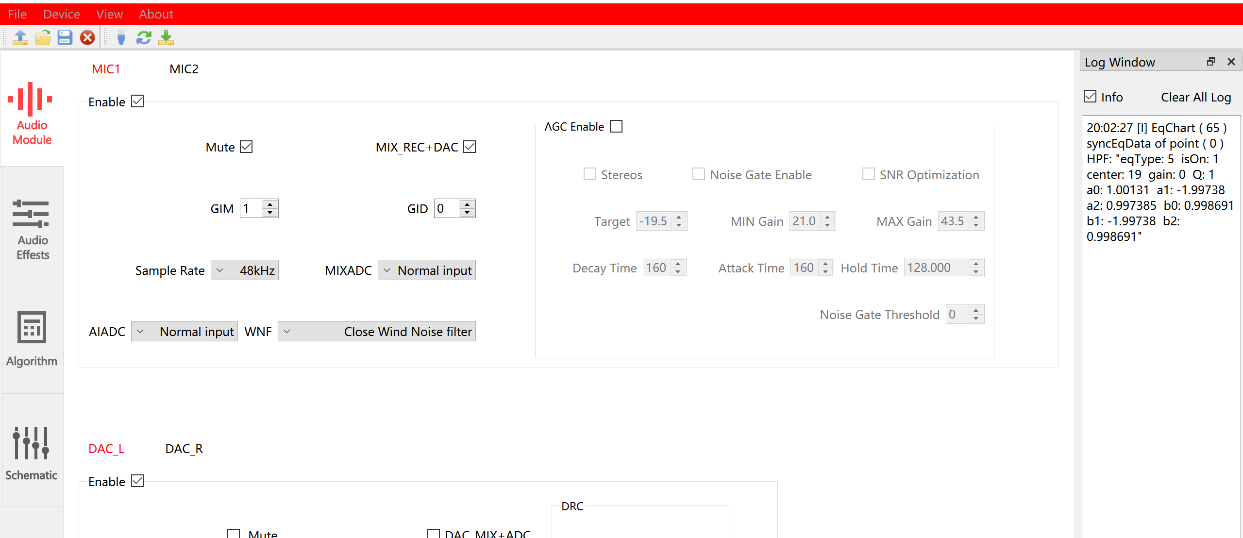
ADC Module allows users to setup audio recording path parameters. EVB supports up to 10 microphones. MIC1 and MIC2 can be used for both digital and analog microphones. The remaining 8 MIC can only be used as a digital microphone interface. Users can also enable the AGC algorithm and dynamically modify the parameters of the algorithm.
Target, Min/Max Gain, Decay/Attack/Hold Time, Noise Gate Threshhold – AGC Parameters
Enable – Enable or disable MIC interface
Sample rate – Sampling rate. Due to software limitations, currently MIC1-10 can only support the same sampling rate
GIM – Analog gain, only applicable when MIC1 and MIC2 is an analog microphone interface
Mixadc – Channel choices of mix record between MIC and DAC, only applicable to MIC1 and MIC2
Mix_REC+DAC – The control of mix record between MIC and DAC, only applicable to MIC1 and MIC2
Noise Gate Enable – Enable noise threshold
SNR optimization – Enable SNR optimization
AGC enable – Enable AGC
Mute – Mute MIC
WNF – Wind Noise Filter
GID – Digital gain
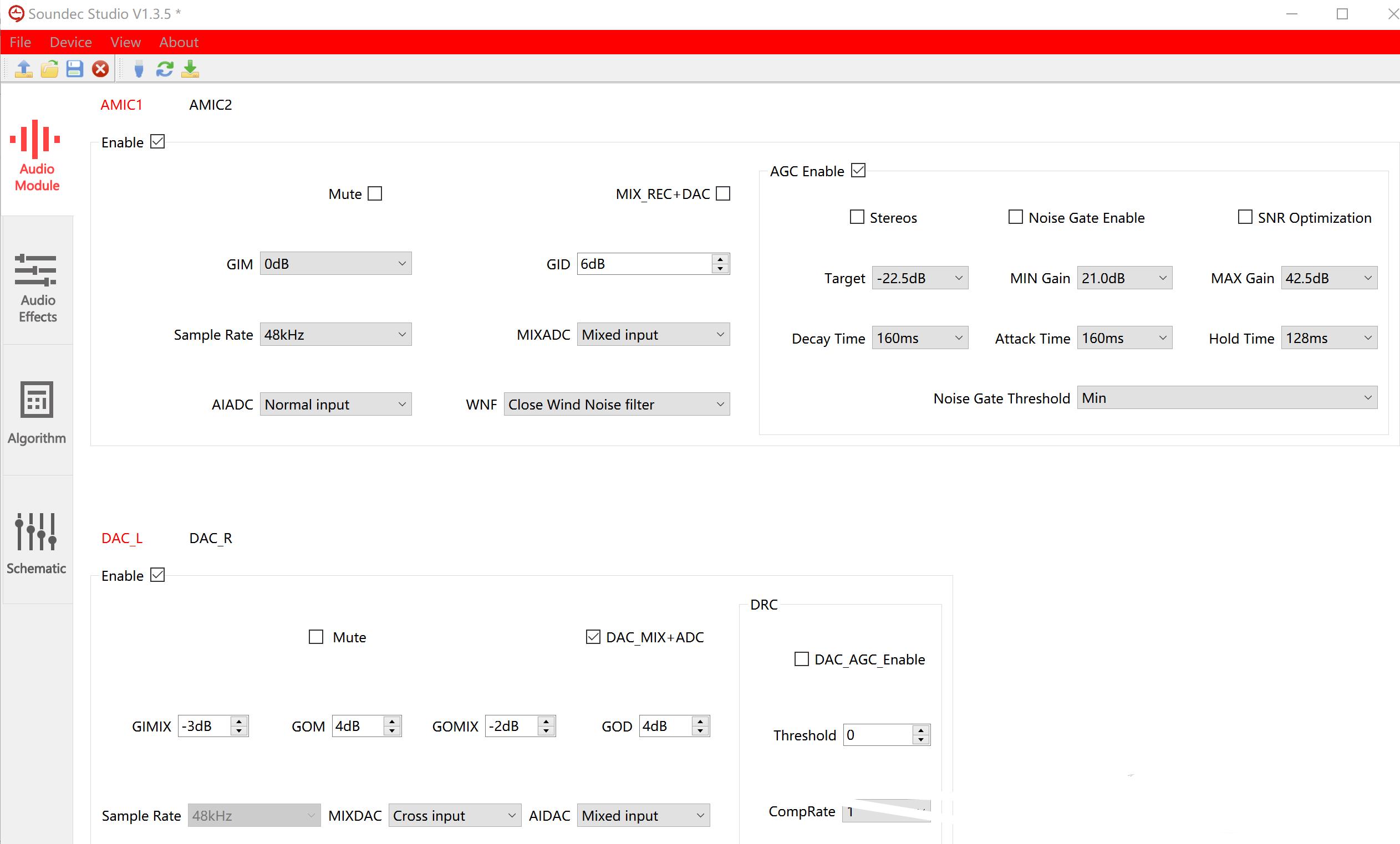
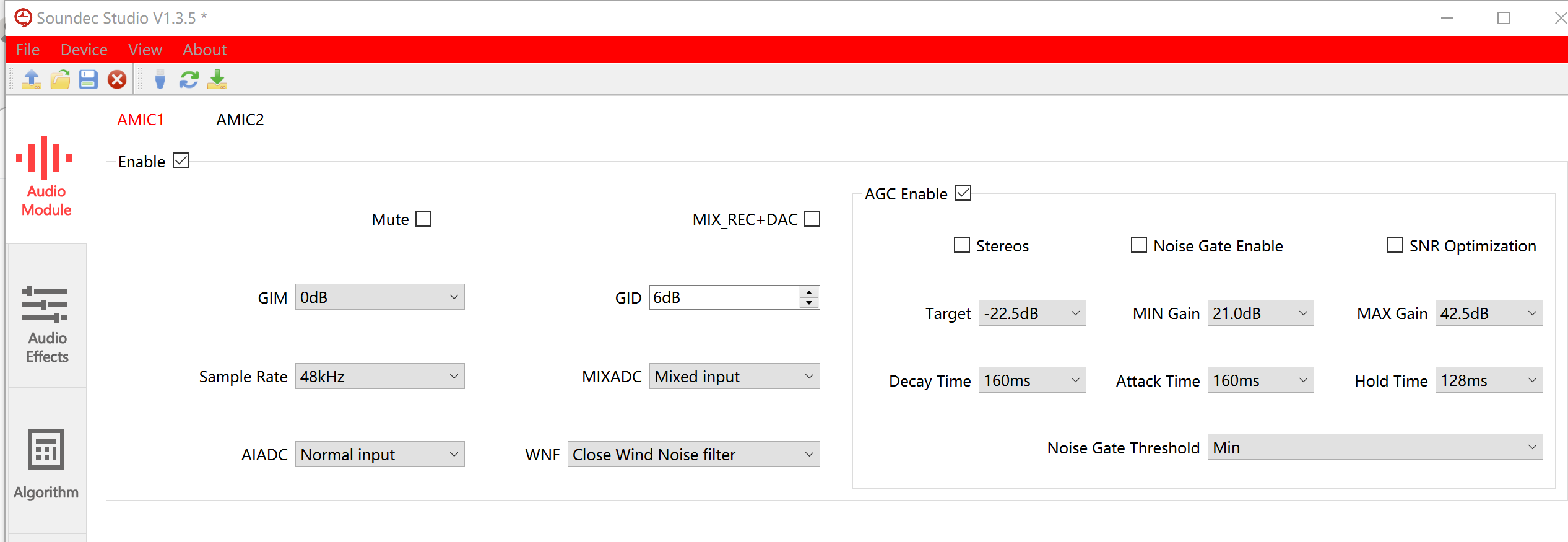
The following figure shows the MIC parameter configuration interface
# DAC
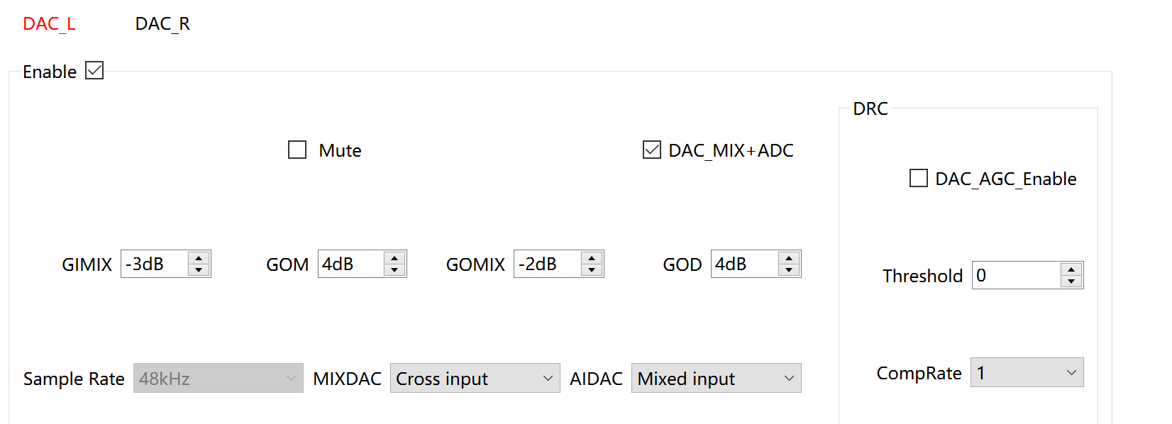
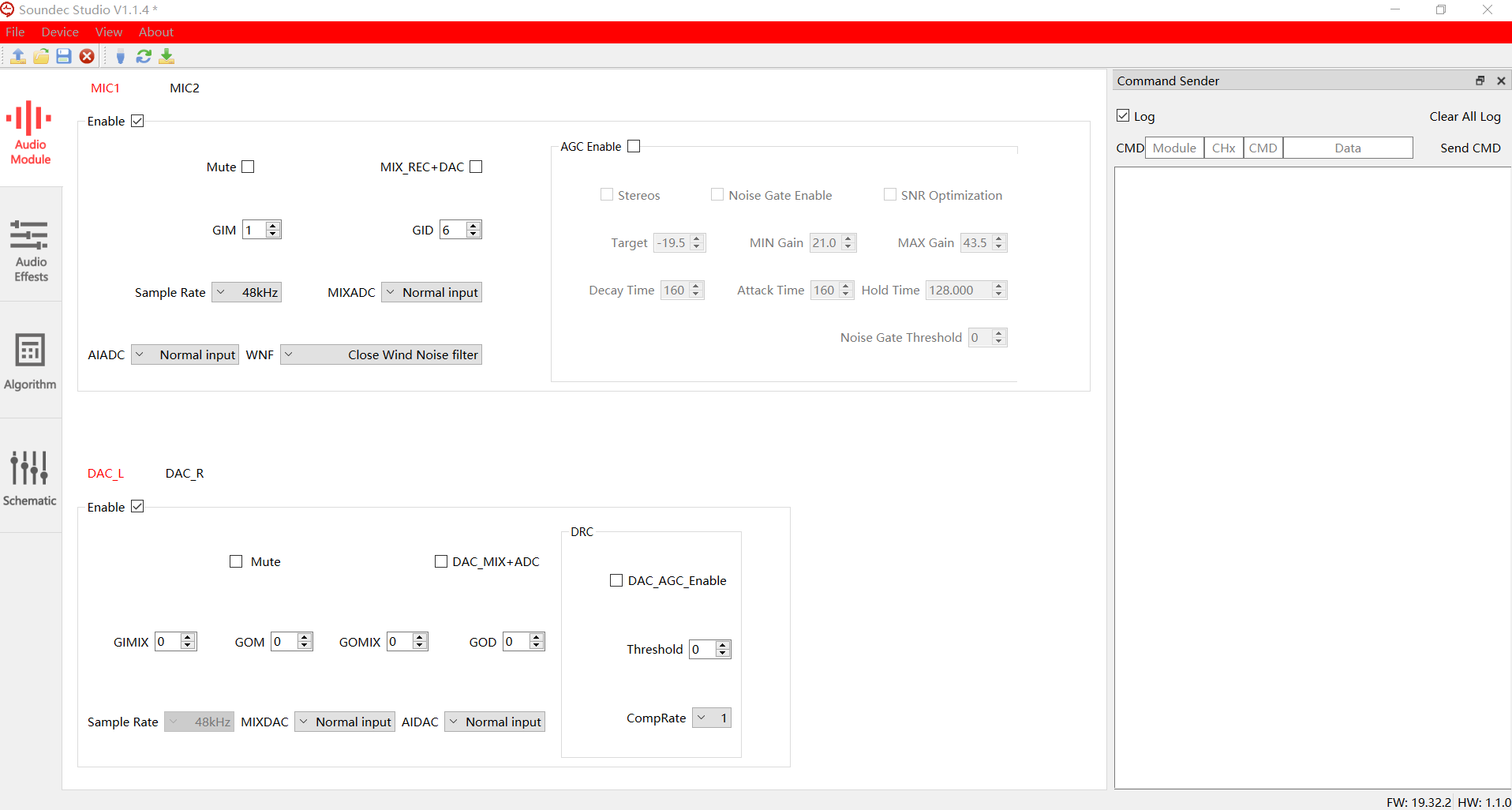
The DAC is the audio output part, which supports left and right channel and DRC(Dynamic Range control).
DAC_MIX_ADC – The control of mix playback between MIC and DAC,
GOM – Analog Gain
GOD – Digital gain
GIMIX – MIC gain when DAC_MIX_ADC is On
GOMIX – DAC gain when DAC_MIX_ADC is On
Mute – Mute DAC
MIXDAC – Channel choices when DAC_MIX_ADC is On
Sample rate – Sampling rate
Enable – Enable DAC
DRC – Enable Dynamic Range Control
The following figure shows the DAC parameter configuration interface
# Equalizer
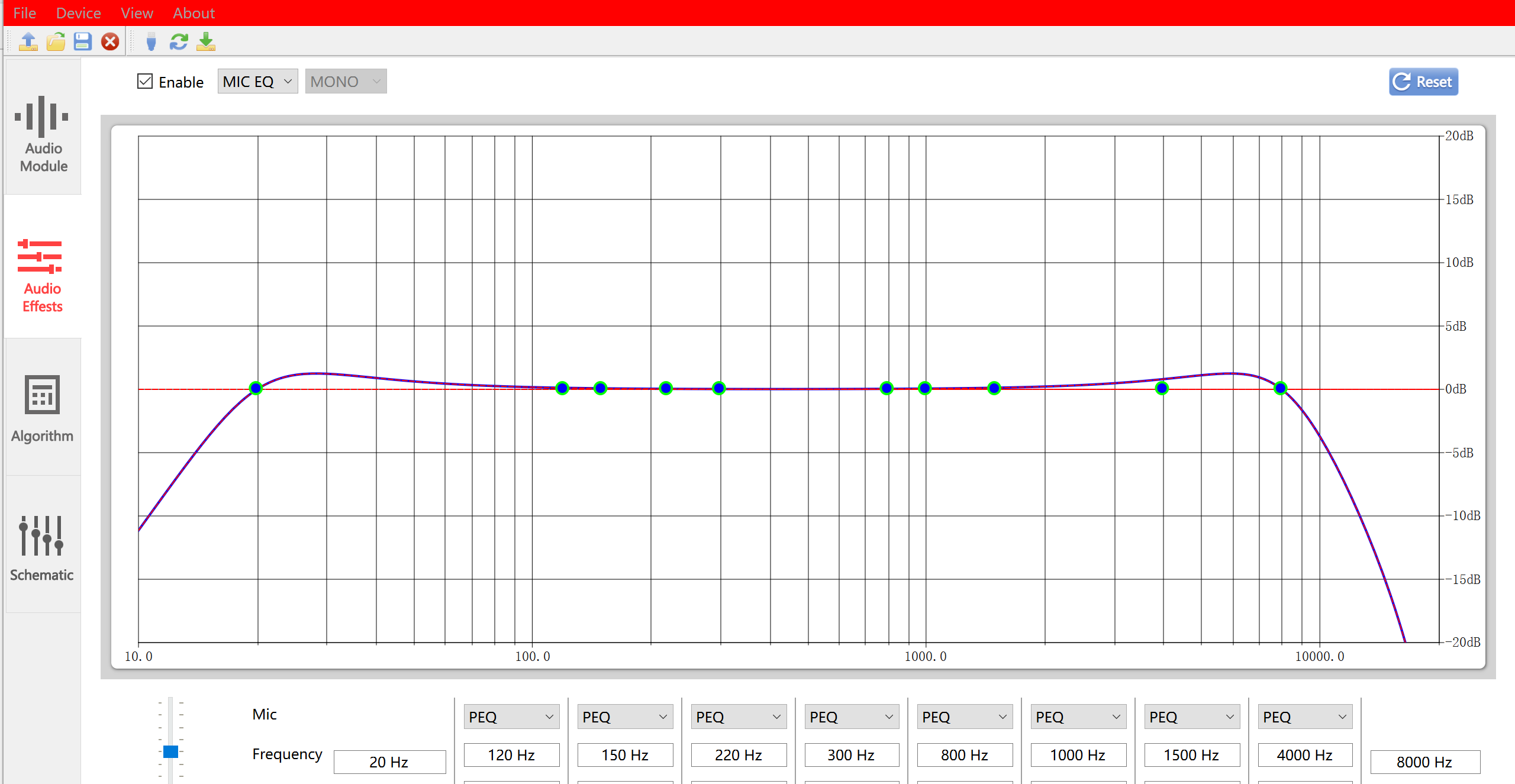
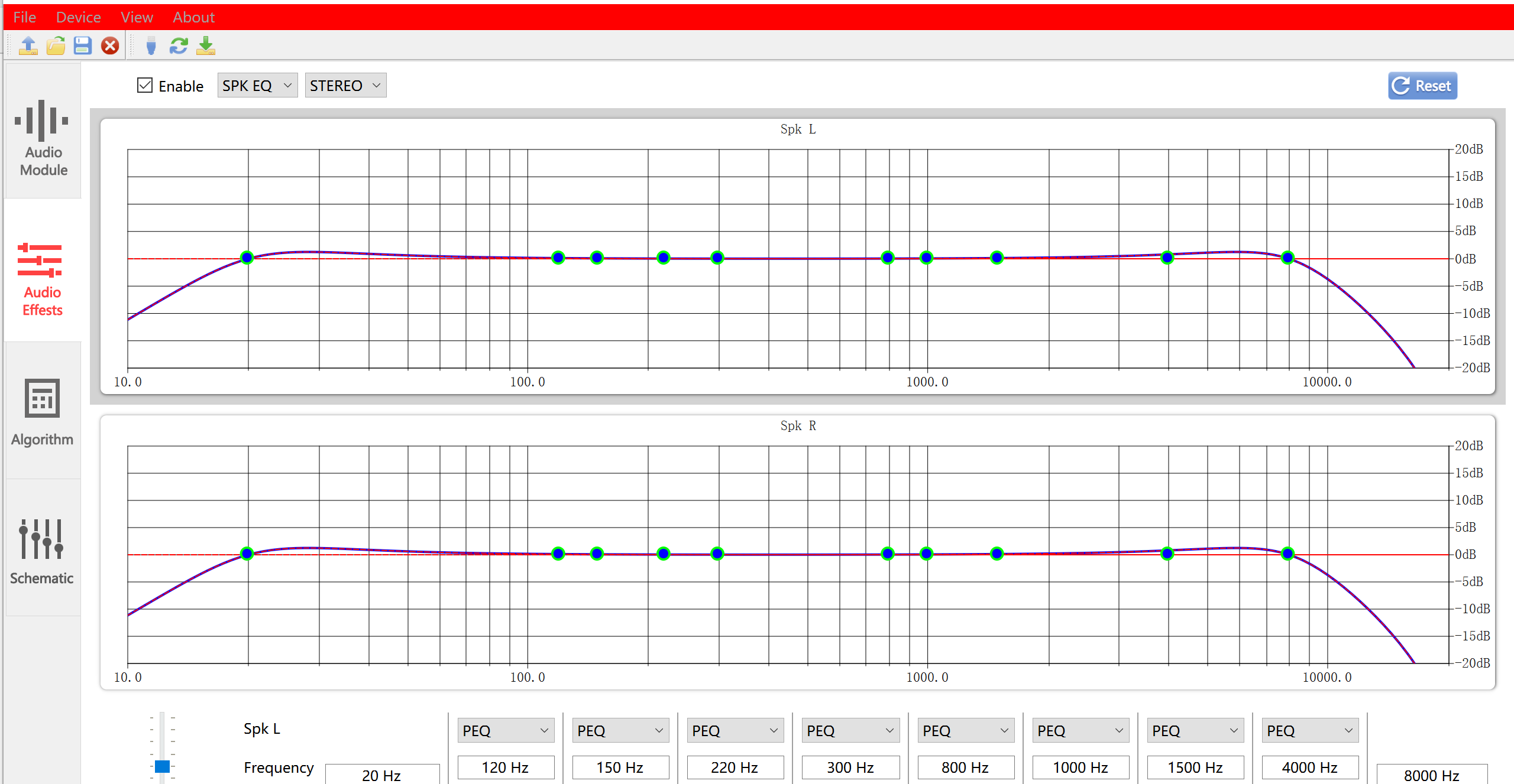
EQ can be divided into MIC EQ and SPK EQ. SPK EQ offers both stereo and mono options. The parameters of EQ are composed of 10 bands with frequencies ranging from high to low, where Band1 and 10 are fixed as LPF and HPF filter, and the middle 8 bands have optional filter types. The parameters of each Band include frequency, gain, and parameters.
The following figure shows the parameter configuration interface of MIC EQ
The following figure shows the parameter configuration interface of SPK EQ
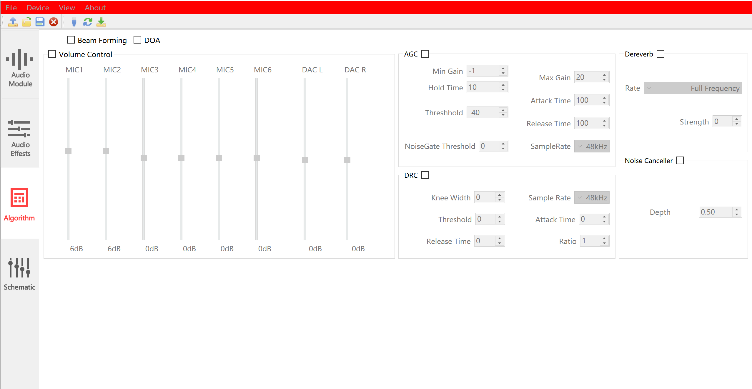
# Algorithm
The algorithm section is used to control the algorithms running on the evaluation board in real-time, and these algorithms are provided with different firmware。
Noise Canceller - Noise Cancllation related parameters
DRC – Dynamic Range Control
AGC – Automatic Gain Control
Dereverb – Dereverb related parameters
Beam Forming – Enable Beam Forming
DOA – Enable Direction of Arrival
The following figure shows the parameter configuration interface for the algorithm section
# Others
# Schematic
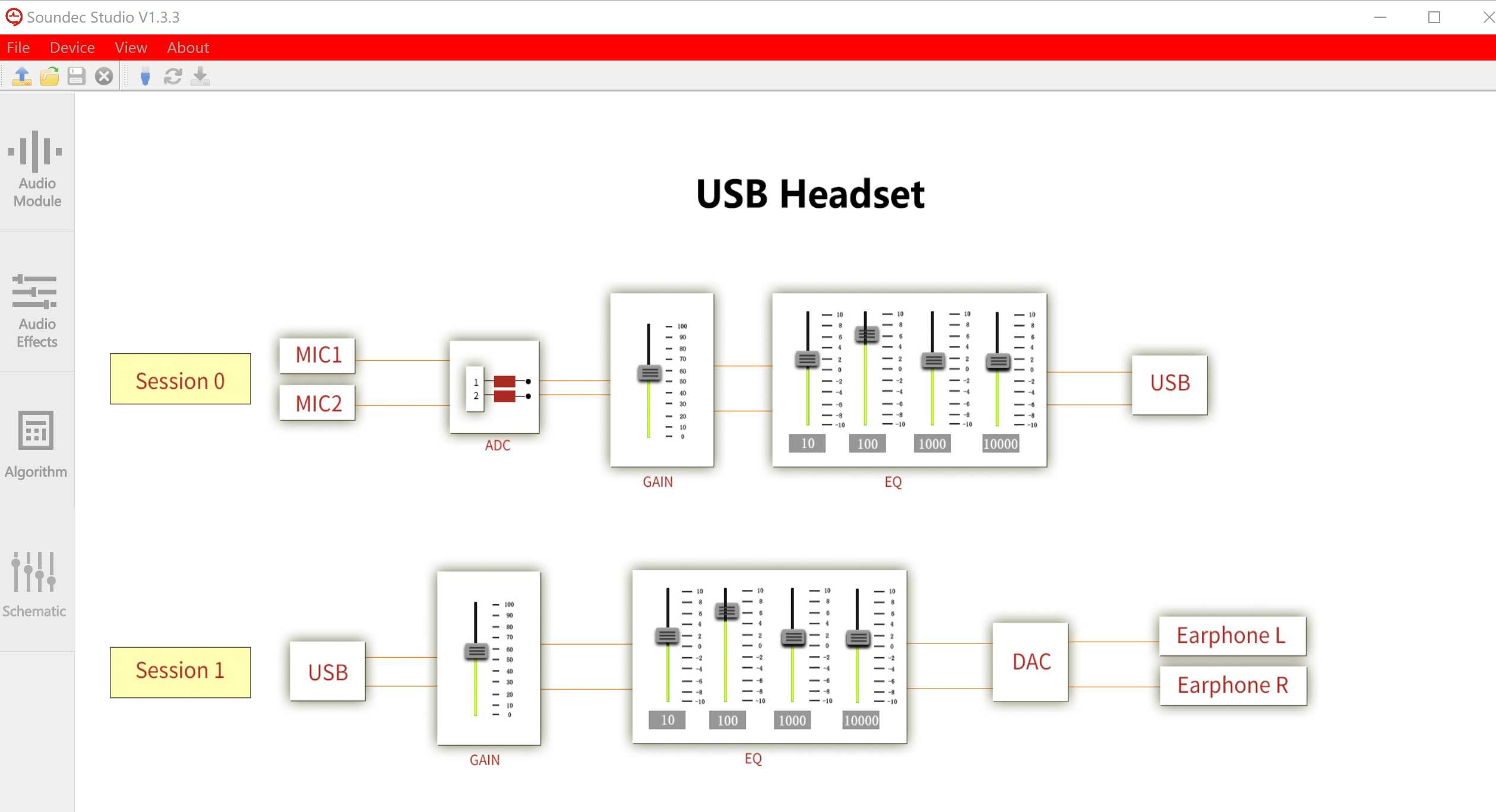
The Schematic page will display the corresponding audio path of firmware burned in the evaluation board. The evaluation board burns USB noise cancellation headphone firmware, and its corresponding audio path diagram is shown below
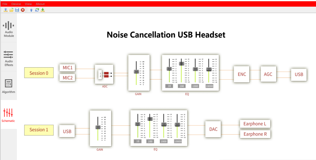
2-session auido path:
Session0 - Audio data from the two microphones is processed by algorithms and output through USB. The GAIN, EQ, ENC, and AGC in the middle are optional algorithms for processing.
Session1 - The data from USB downlink is output through DAC, and there will also be algorithms such as GAIN, EQ, and DAC processing.
# Log Window
Open View in the Soundec Studio menu bar, select the Log Window menu, and a Log Window window will pop up on the right side of the interface. Check Info and adjust various parameters to see the operation log in the Log Window.
# Command Sender
Open View in the Soundec Studio menu bar, select the Command Sender menu, and a Command Sender window will pop up on the right side of the interface. Check Log, then enter the corresponding command's Module, Chx, CMD, Data and other parameters (hexadecimal, without the prefix of 0x), click Send CMD, and you can see the sent command in Command Sender.
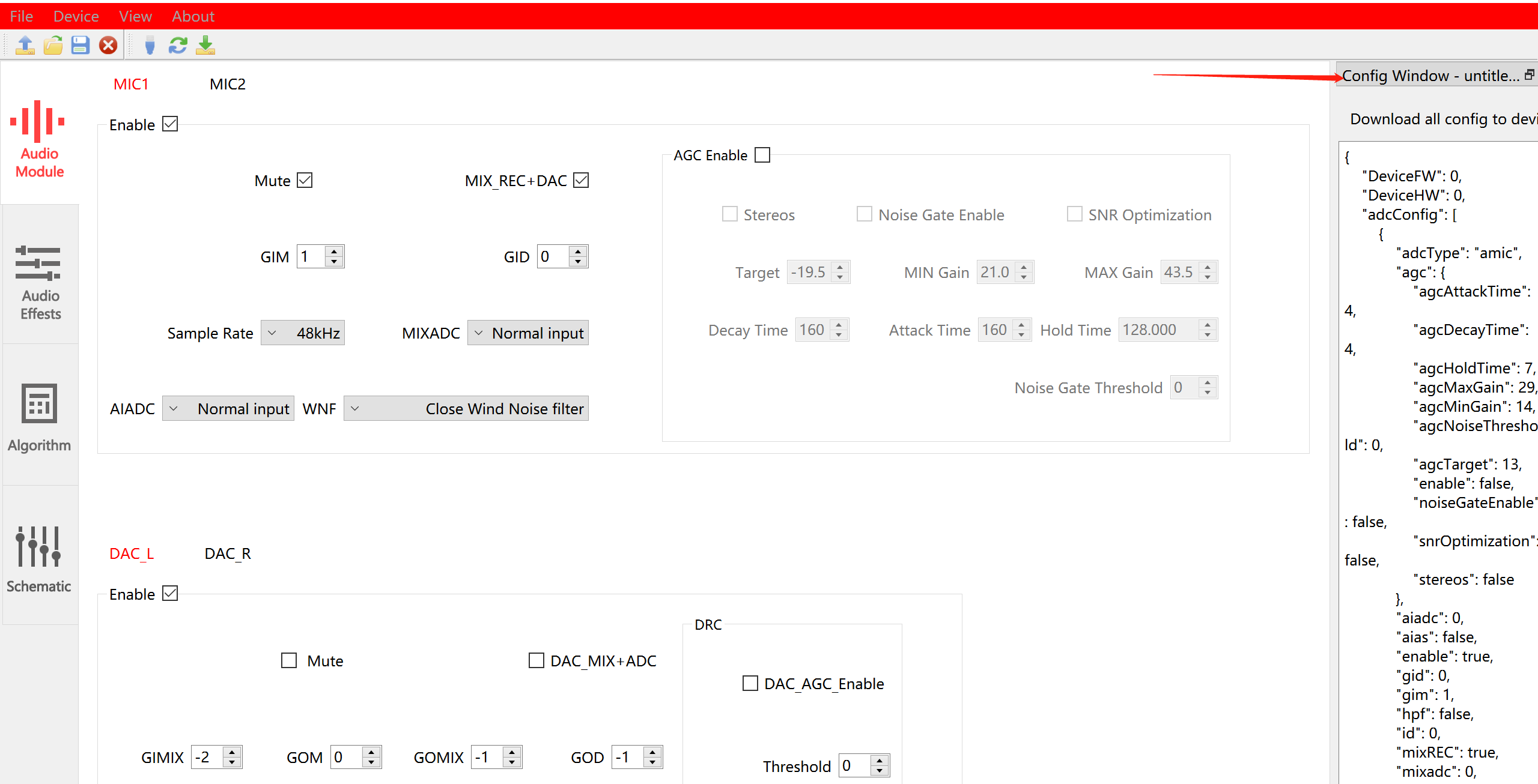
# Config Window
Open View in the Soundec Studio menu bar, select the Config Window menu, and the Config Window window will pop up on the right side of the interface.
You can see the structured data of the opened .flex file in the Config Window.
# Software Upgrade
Open View in the Soundec Studio menu bar, select the Check for Updates menu, and Soundec Studio will check for new versions. If there is a new version, an upgrade prompt will appear.
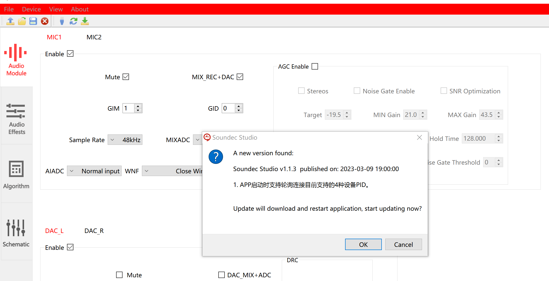
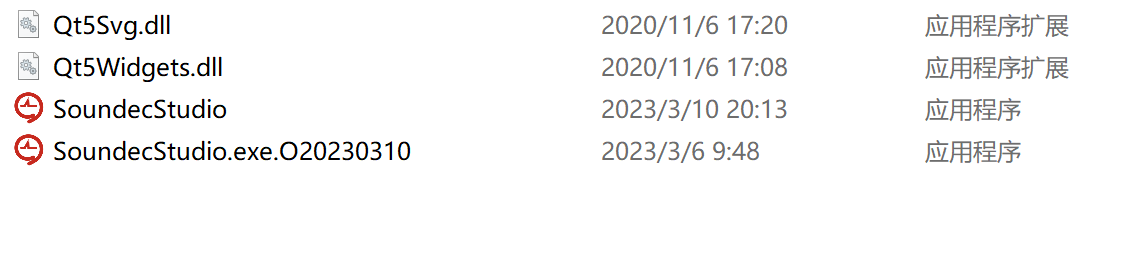
Click OK and Soundec Studio will automatically upgrade. After completion, the application will restart. You can also run "SoundecStudio.exe" in the directory where SoundecStudio is located. (The files without suffixes are the latest exe files, while those with suffixes are old versions. Once confirmed as unnecessary, they can be deleted)
# Download Soundec Studio
Please downlod "Soundec Studio" in following link
# Example 1 - USB Noise Cancellation Headset
# Features
MIC AGC, automatic gain control to achieve ideal sound state, avoiding noise and automatically amplifying sound signals when the sound is discontinuous or low
SNC8600, professional digital signal processing DSP with built-in ENC noise reduction processing technology, effectively shielding background noise, with a noise reduction depth of up to 60 ± 3dB
High speed USB2.0, supporting uac2.0/1.0 adaptation, compatible with new and old upper computer devices
Clear digital voice call, clear and transparent voice, highly reproducible human voice
Support Speaker EQ to make sound and music more full
MIC 8-segment hardware EQ, configured with specialized sound
Supports Microsoft Teams and Tencent conference certification
Dual microphone, active noise reduction
Can support commonly used button functions
Support for ear return function
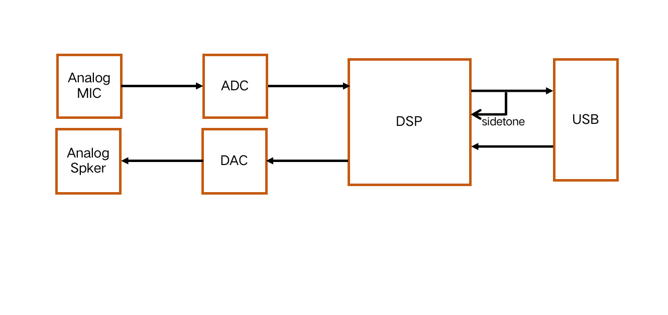
# Audio Path
The following figure shows the audio path of USB noise cancellation headset
# Microphone and microphone rod specifications
MIC protection: The sound pickup microphone needs to be equipped with a windproof surface to effectively prevent breathing sounds. Attention should be paid to opening and sealing of microphone. microphone holes and back covers should avoid forming cavities that affect the noise reduction effect
MIC position: The sound pickup microphone is located on mic rod and near to the mouth, and the noise reduction microphone is located on the earphone cover at a distance from the sound pickup microphone
AOP (Acoustic Overload Point): >120dB SPL, the maximum sound pressure value that can be withstood when the THD is less than 10%
Sensitivity: Pickup microphone: -40dB, accuracy ± 1dB, noise reduction microphone: -40dB, accuracy within ± 1dB
Ensure that the frequency response curve, impedance, distortion, and phase of the pickup microphone and noise reduction microphone are consistent
It is necessary to screen the sensitivity of the pickup mark and noise reduction mark to ensure consistent accuracy between the two
Frequency response curve requirements: The frequency response curve of 20-20KHZ should be relatively flat, with minimal attenuation
SNR (Signal-to-Noise Ratio): noise reduction MIC SNR ≥ -60dB, the higher the signal-to-noise ratio, the better
PSRP (Power Suppression Ratio): The higher the better. It is recommended that the silicon microphone be above 58dB
Directionality: polar microphone - single directional, noise reduction microphone - full directional
THD ≧94dB
Mic rod length: 16cm
# Recommendations for microphone and speaker parameters
The following figure lists the recommended microphone and speaker parameters

# Example 2 - Conference System
# Features
Excellent acoustic performance, capable of achieving clear pickup within a radius of 1-5 meters, suppressing background noise (including steady-state and non-stationary), dual talk echo cancellation, and de reverberation, among other main functions
Excellent performance under the strong computing power and sufficient memory support of the SNC8x series ; Suitable for meeting rooms of different sizes, meeting the needs of multi-person conversations
Soundec microphone array solution, covering 2 microphone and 4 microphone arrays
Using SNC8600 professional audio processor
Single chip integrated USB PHY and UAC audio services, with significant cost advantages
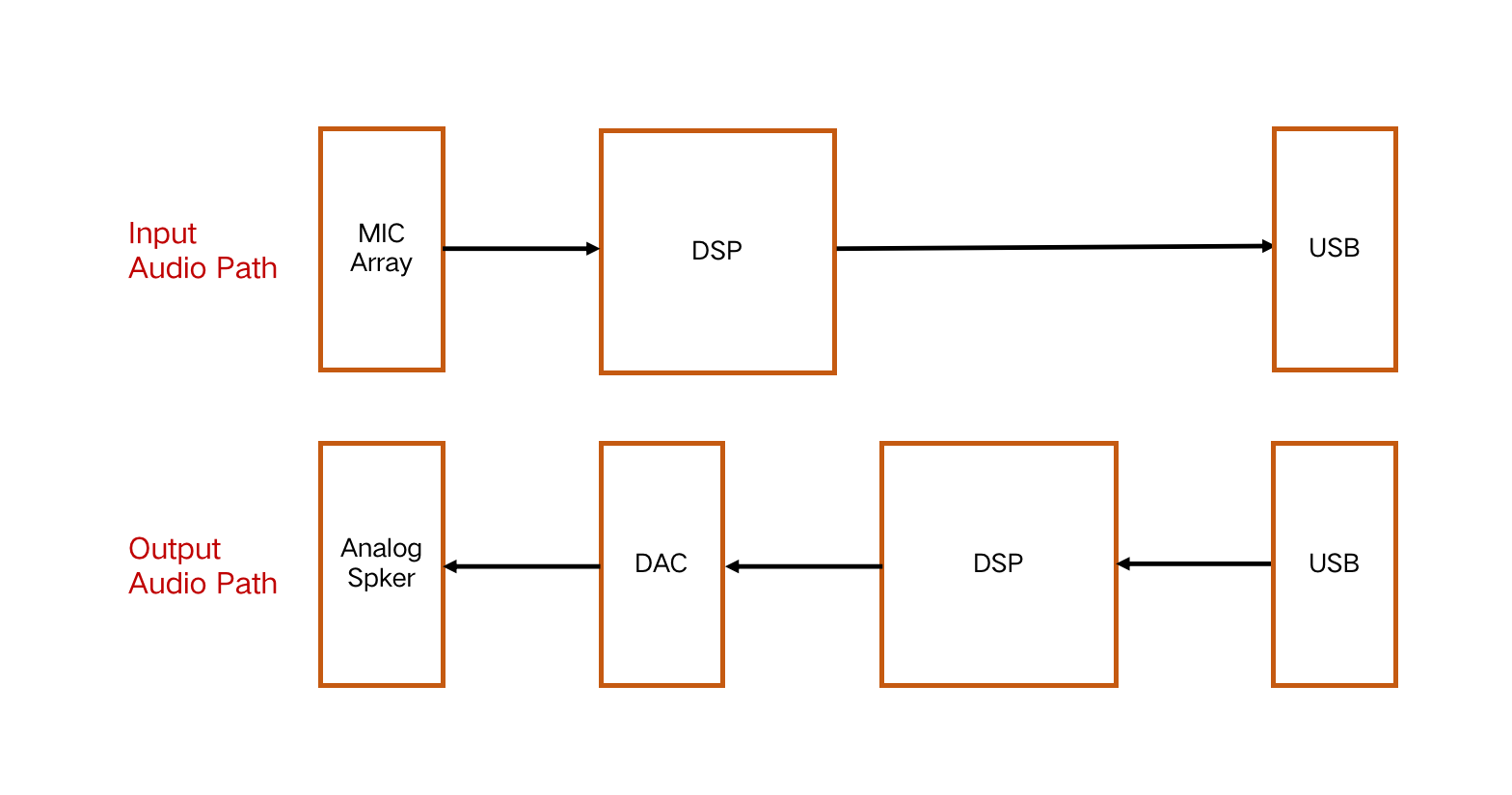
# Audio Path
The following figure shows the audio path of Conference System
# Acoustic performance
Pickup distance: 1-5 meters, consistent loudness
Noise reduction depth: -56dB (average RMS)
Echo cancellation depth: -80dB (average RMS)
Reverberation suppression depth: -46dB (average RMS)
# Microphone and speaker specifications
Microphone input method: recommended for under input, structurally easier to seal
The following figure lists the recommended microphone parameters
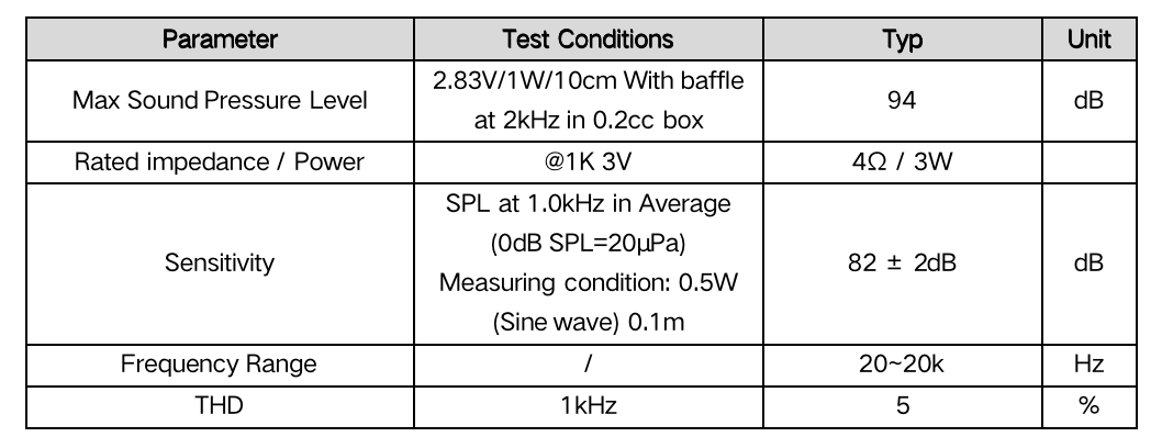
The following figure lists the recommended speaker parameters
# Example 3: Bluetooth Conference System
# Features
Excellent acoustic performance, capable of achieving clear pickup within a radius of 1-5 meters, suppressing background noise (including steady-state and non-stationary), dual talk echo cancellation, and de reverberation, among other main functions
Excellent performance under the strong computing power and sufficient memory support of the SNC8x series ; Suitable for meeting rooms of different sizes, meeting the needs of multi-person conversations
Soundec microphone array solution, covering 2 microphone and 4 microphone arrays
Using SNC8600 professional audio processor
Single chip integrated USB PHY and UAC audio services, with significant cost advantages
Communication modules that can connect to different Bluetooth protocols through I2S and I2C or serial ports
# Acoustic performance
Pickup distance: 1-5 meters, consistent loudness
Noise reduction depth: -56dB (average RMS)
Echo cancellation depth: -80dB (average RMS)
Reverberation suppression depth: -46dB (average RMS)
# Audio Path
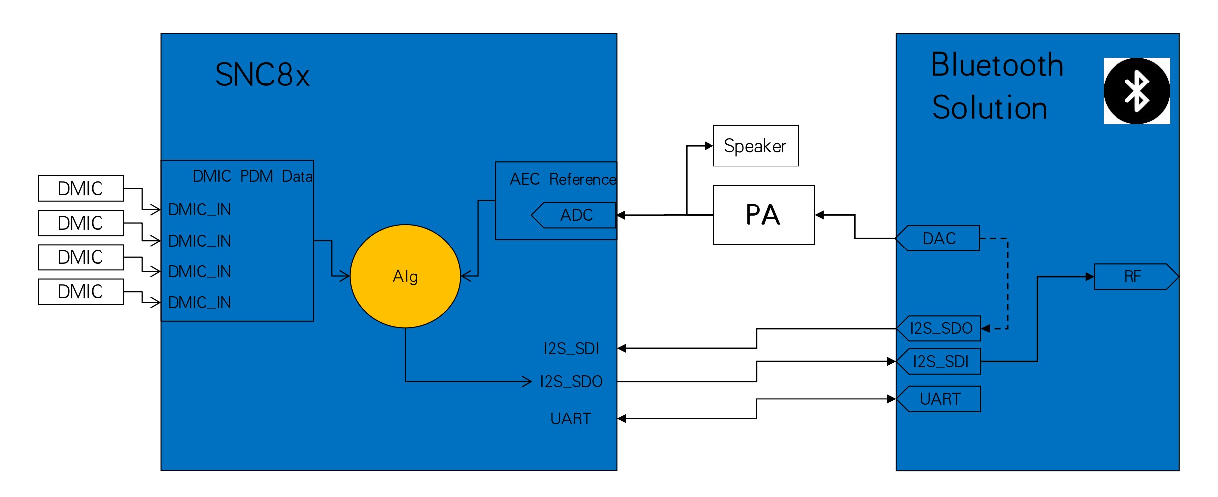
The following figure shows the audio path of Bluetooth Conference System
# Microphone and speaker specifications
Microphone input method: recommended for under input, structurally easier to seal
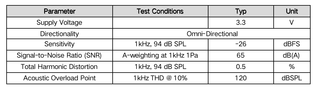
The following figure lists the recommended microphone parameters
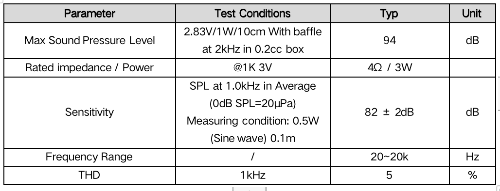
The following figure lists the recommended speaker parameters
# Example 4: Wireless Noise Cancellation Microphone
# Features
Wireless lavalier type noise reduction microphone application, suitable for various scenarios such as live streaming, shooting, recording, etc., supporting dual microphone directional pickup, environmental noise reduction, and clear vocal pickup
The noise reduction switch can switch between two modes: noise reduction and original sound. The noise reduction mode operates simultaneously with dual microphones, allowing for directional pickup and environmental noise reduction. The original sound mode allows for omnidirectional pickup
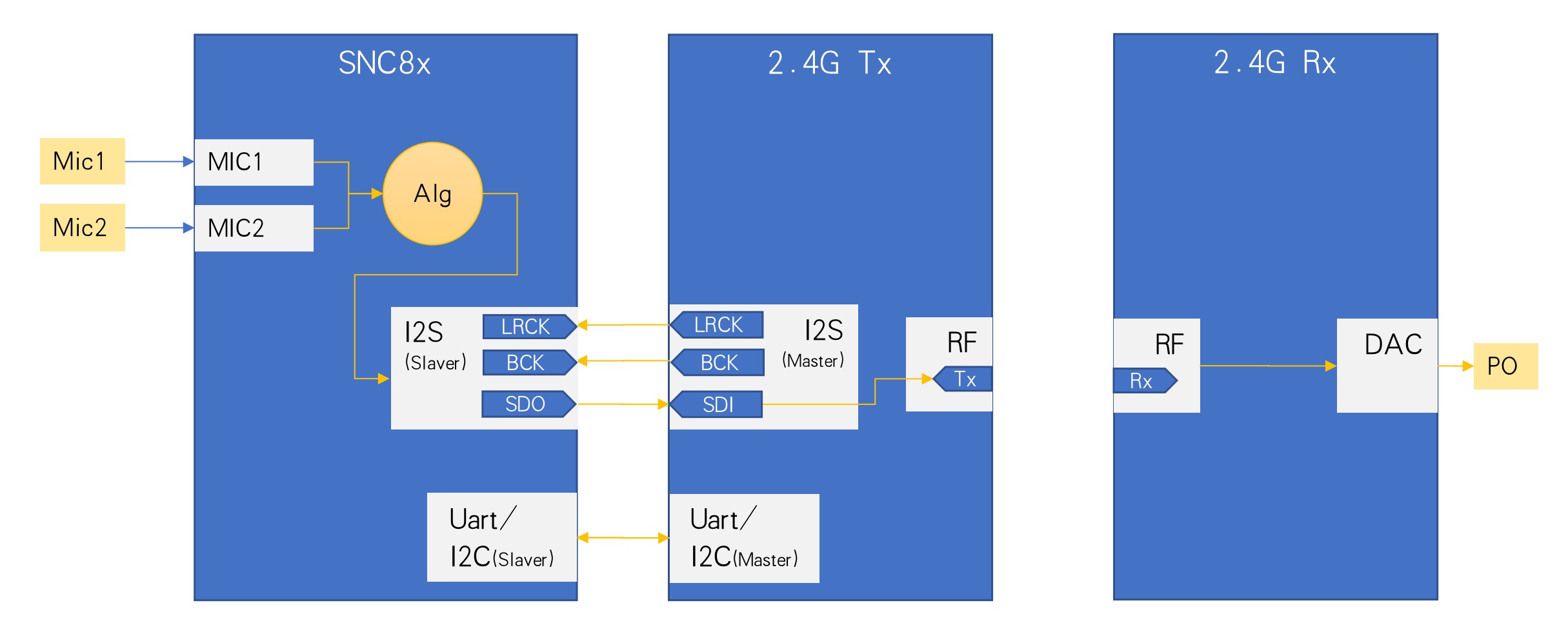
The transmitter and receiver are used together. The transmitter is connected to a dual microphone array, and the receiver is connected to buttons, headphone monitoring output, and USB output
The distance button can adjust the noise reduction depth in the noise reduction mode and the pickup distance in the original sound mode
Equipped with 2.4G module, automatic connection without pairing, faster transmission and more stable reception
USB high resolution digital audio output, suitable for various devices such as computers, phones, cameras, etc
Real time monitoring, real-time adjustment while recording and listening
# Acoustic performance
Pickup angle: 90 ° C (noise reduction mode)/180 ° (original mode)
Dual microphone noise cancellation FS: 48K
Noise reduction depth: 40dB
SNR: >74dB
# Audio Path
The following figure shows the audio path of Wireless Noise Cancellation Microphone
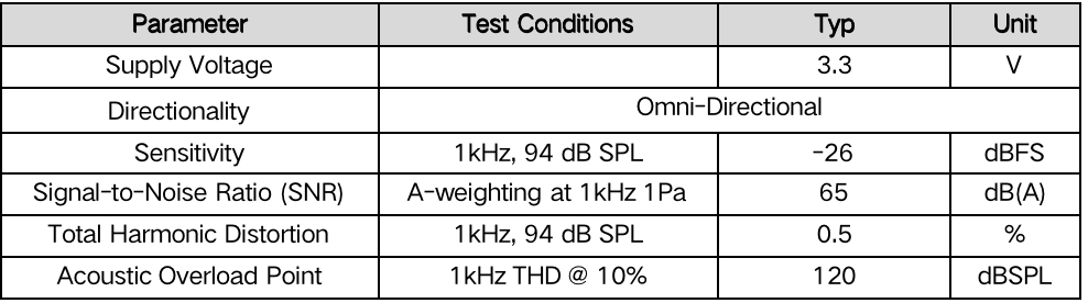
# Microphone specifications
Microphone input method: recommended for under input, structurally easier to seal
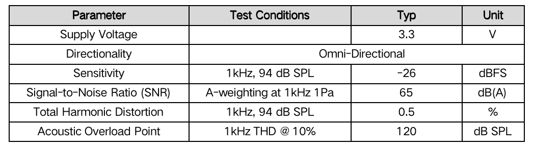
The following figure lists the recommended microphone parameters
# Schematic design suggestions
If using host, host shall set POWER_ON to high leval via GPIO and connect VBAT power supply to SNC8xx power supply pin AVD_PWR_ESR/AVD_PWR_RAR. It can control power supply of SNC8x processor, as shown in the following figure
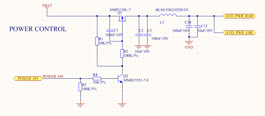
When the SNC8x processor is not powered on, host set DFU pin to low level first and then power it on to enter DFU mode. As shown in the following figure
USB interfaces (DP, DM, GND) can be used for algorithm debugging;
Serial ports (RX, TX, GND) can be used for software debugging;
# Example 5: USB Desktop Microphone
# Features
USB desktop microphone, suitable for various pickup scenarios such as online live streaming, professional recording, and home karaoke, supporting real-time monitoring and real-time adjustment while recording
SNC8x single chip solution. USB connected device, supports computers, phones, tablets, etc., built-in sound card, plug and play without the need for driver installation
Support environmental noise reduction, effectively suppress environmental noise, reduce room acoustic environmental requirements, and easily pick up clean human voices
Supports high-definition pickup with up to 192K sampling rate and 24 bit accuracy, enabling Hi-Res recording
Support for headphone amplifier and microphone volume knob adjustment, convenient gain control
Support Windows, Mac, Android devices
# Acoustic performance
Sampling rate: 48K (noise reduction mode)/192K (Hi-Res mode)
Pickup angle: omnidirectional
Noise reduction depth: ≥ 25dB
SNR: >74dB
THD: < 3%
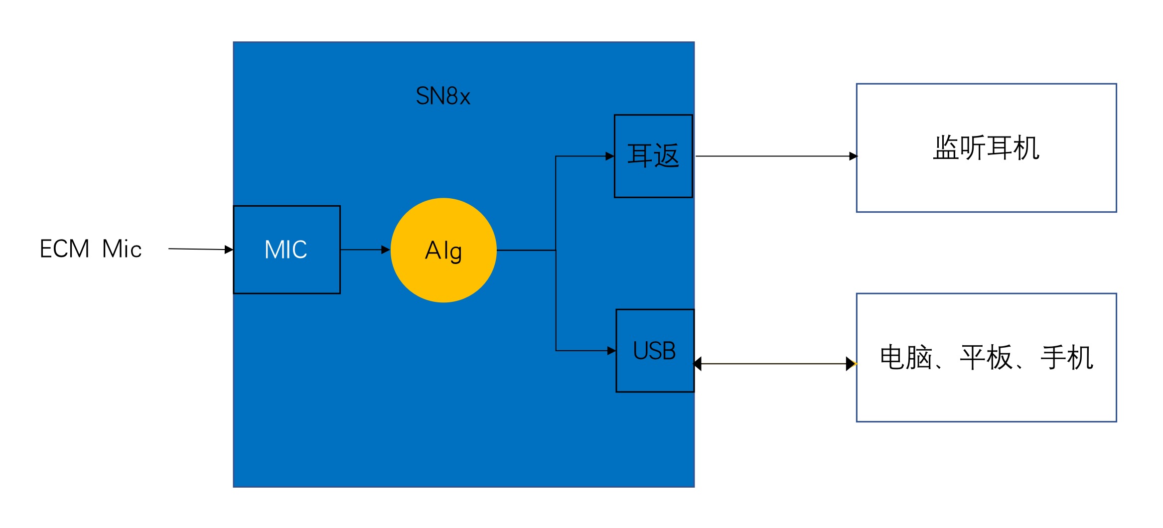
# Audio Path
The following figure shows the audio path of USB Desktop Microphone
# Microphone specifications
It is recommended to use an electret microphone.The following figure lists the frequency response curve of the recommended microphone:
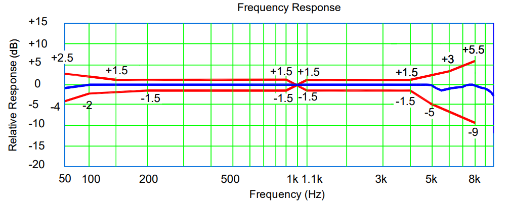
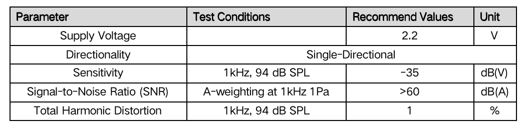
The following figure lists the recommended microphone parameters
# Schematic design suggestions
If using host, host shall set POWER_ON to high leval via GPIO and connect VBAT power supply to SNC8xx power supply pin AVD_PWR_ESR/AVD_PWR_RAR. It can control power supply of SNC8x processor, as shown in the following figure
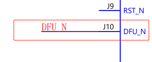
When the SNC8x processor is not powered on, host set DFU pin to low level first and then power it on to enter DFU mode. As shown in the following figure
USB interfaces (DP, DM, GND) can be used for algorithm debugging;
Serial ports (RX, TX, GND) can be used for software debugging;
# Example 6:USB Earphone Amplifier
# Features
SNC8x series single chip provides a universal audio solution for USB earphone amplifier applications
High performance DAC, supporting up to 24bit, 192K sampling rate, SNR ≥ 110
Supports hardware 8-band EQ, with 3 built-in sound effects, and supports user-defined sound effects
On-chip USB PHY, supporting UAC 1.0/2.0 audio service, button switching UAC 1.0: 44.1k/48k/88.2k/96k/176.4k/192k, 16bit/24bit UAC 2.0:44.1k/48k/88.2k/96k/176.4k/192k, 16bit/24bit/32bit
Sound mode: supports the following three modes, as well as user-defined modes Cinema mode: dynamic high and low frequency enhancement, cinema level experience Music mode: matching the audio characteristics of different earphones Direct mode: lossless amplification
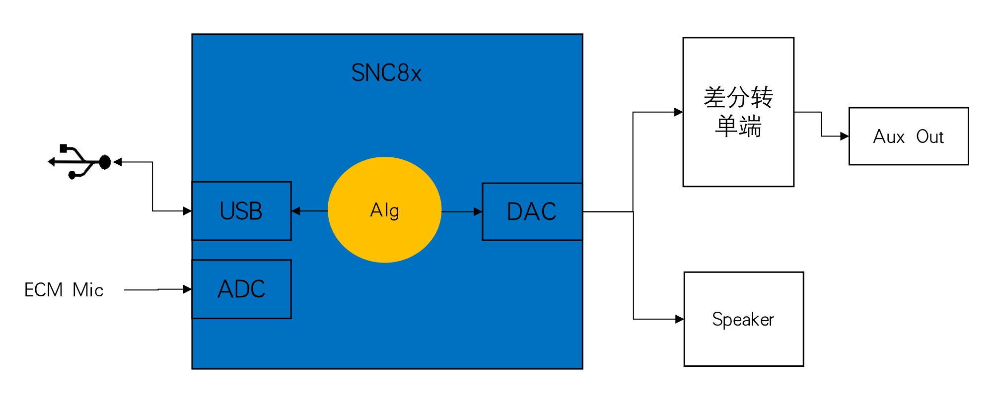
Analog output: balanced output, or balanced to single end
Light effect: PWM control for multiple light effects
# Acoustic performance
Output: 1Vrms@16 Ω/ 2Vrms@32 Ω
Interface type: Type-C to 3.5mm/4.4mm
THD: <0.0015%
Dynamic Range: 110dB
# Audio Path
The following figure shows the audio path of USB Earphone Amplifier
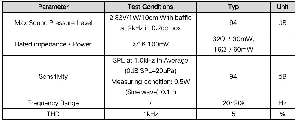
# Speaker specifications
The following figure lists the recommended microphone parameters
# Schematic design suggestions
If using host, host shall set POWER_ON to high leval via GPIO and connect VBAT power supply to SNC8xx power supply pin AVD_PWR_ESR/AVD_PWR_RAR. It can control power supply of SNC8x processor, as shown in the following figure
When the SNC8x processor is not powered on, host set DFU pin to low level first and then power it on to enter DFU mode. As shown in the following figure
USB interfaces (DP, DM, GND) can be used for algorithm debugging;
Serial ports (RX, TX, GND) can be used for software debugging;