# Software Development Kit Architecture
The target audience of this document is the development engineers who will use the SNC8X series professional audio processor. This document will use SNC8600 as an example to illustrate the software architecture of the SNC8X series audio processor, as well as the interfaces and template files for audio application customization.
Please refer to the product comparison table for the complete SNC8X (opens new window)series processor.
# Architecture
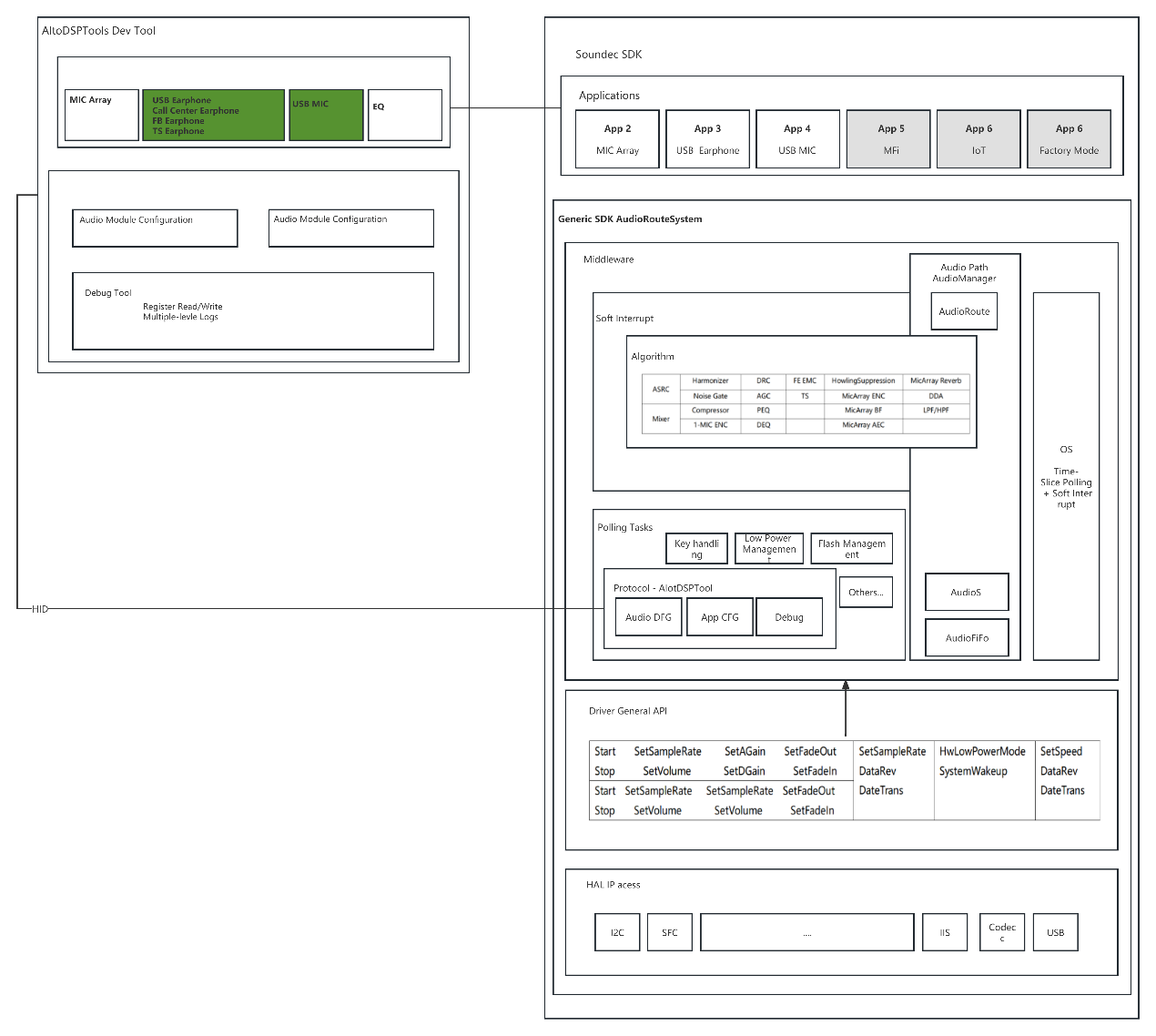
Soundec Studio provides the development and debugging functions on the PC side, while SOUNDEC SDK provides the complete software runtime environment on the firmware side.
The SOUNDEC SDK is divided into 3 layers from top down: the application layer, the Framework layer, and the driver layer:
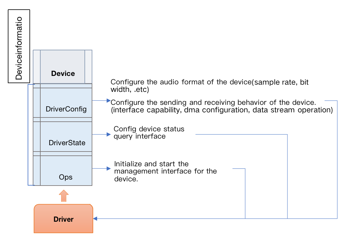
The bottom layer provides the complete HAL and driver modules, the HAL is provided in the form of .a library, and the driver module provides a unified interfaces for device load, start, and various set and get operations on top of HAL interface.
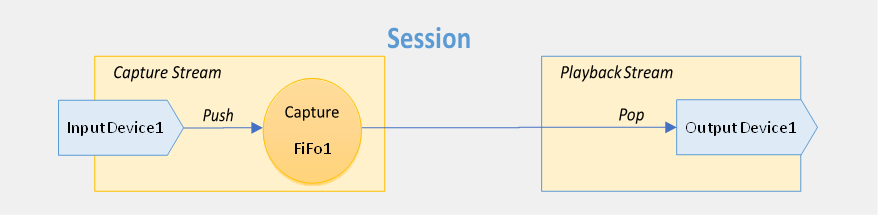
The middle layer is based on Audio Manager, which uses Audio Device to load the device drivers, and use Audio Session to manage the input and output of PCM data streams between audio devices.
The application layer provides Audio Device/Session-based template files for different audio user cases, allowing developer to quickly extend and customize the specific audio application.
In most cases, the template files can be modified easily, thus can quickly build the customized audio chain for specific audio application scenarios. It is the preferred method to use the SDK. Of course, developer can also ignore the application template files, use the Audio Manager interfaces directly to create the corresponding audio chain instead. This requires a decent familiarity with the internal architecture of the SDK and it's not easy to achieve the rapid development.
# The Middle layer -- Audio Manager
Audio Manger employed the Device/Session scheme, is the core of the entire middle framework layer, and well positioned for audio processing. According to the application's audio parameters, developers only need to configure audio session description files, the Audio Manager will automatically load the corresponding audio devices, configure the parameters, and create multiple incoming and outgoing audio streams.
# Device/Session
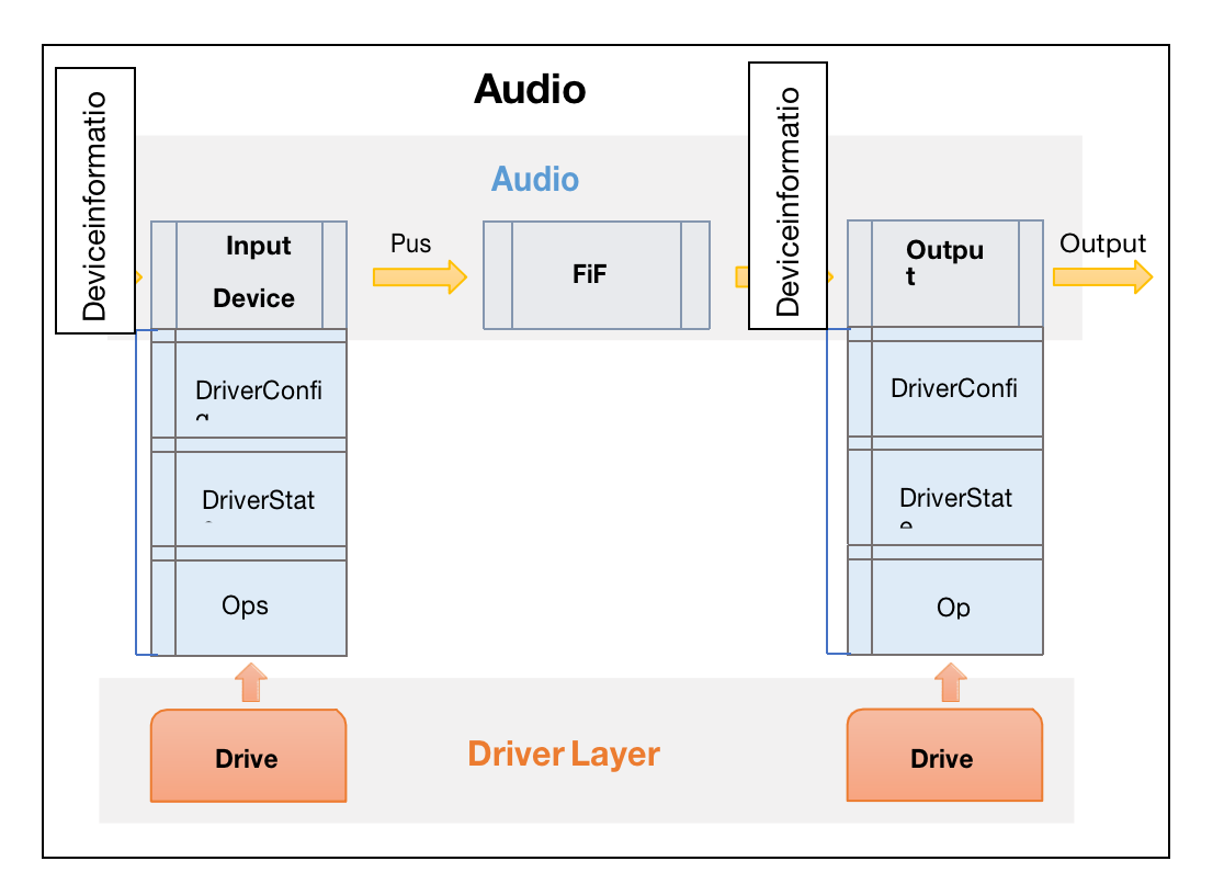
# Device
# Session
- Single input -- Single output
- Single input -- multiple outputs
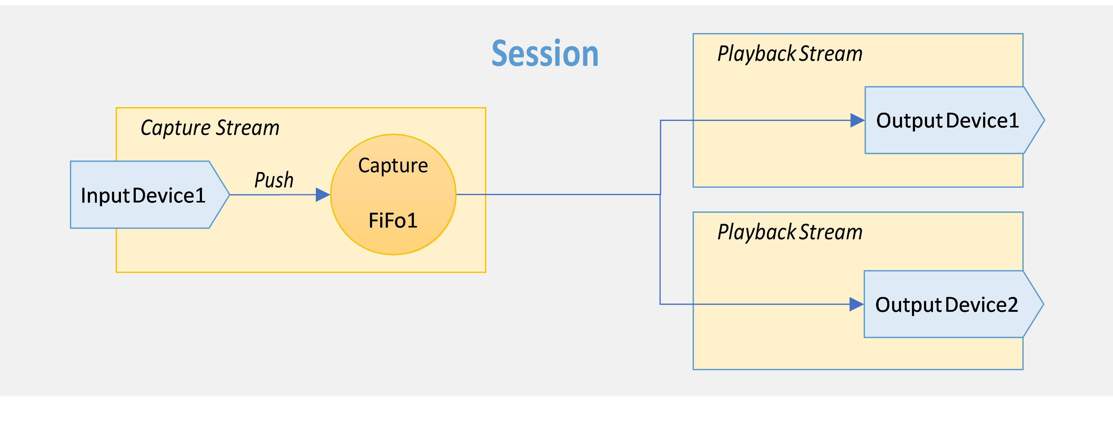
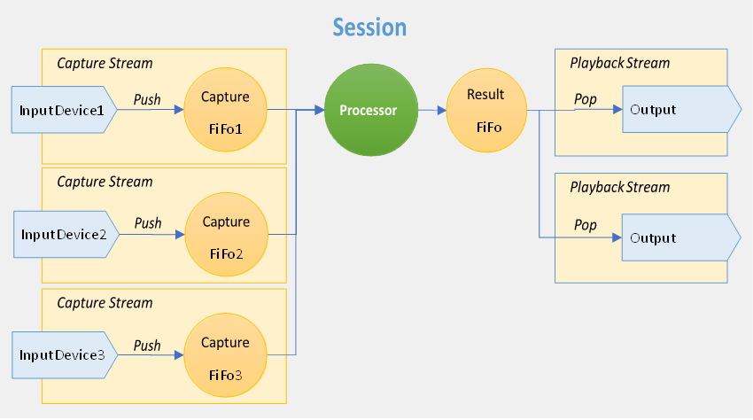
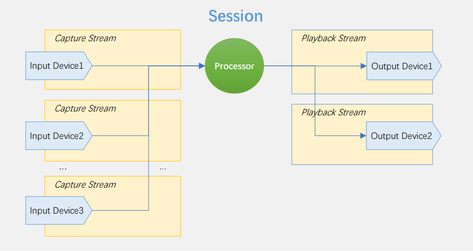
- Multiple Inputs – Multiple Outputs
# Processing flow
Audio Manager performs the following actions based on the configuration file provided by the developer.
# register hardware/load audio devices
The interface for registering hardware device is shown in the file audio_hw_desc.c, through which auDeviceIfs array is defined for different audio devices and their descriptors including Codec (ADC&DAC), I2S, USB (Mic&Speaker), etc.
audioDevIf_t auDeviceIfs[AUDIO_DEVICE_MAX] = {
#if (CODEC_ADC_ENABLE)
	{
		.id = AUDIO_DEVICE_ADC_IN,
		.load = FALSE,
		.name = "adc",
		.rxCfgs = &auDrvCfg_adc,
		.txCfgs = NULL,
		.state = &auDrvSt_adc_in,
		.ops = &auDrvOps_adc_in,
	},
#endif
#if (CODEC_DAC_ENABLE)
	{
		.id = AUDIO_DEVICE_CODEC_OUT,
		.name = "codec",
		.load = FALSE,
		.rxCfgs = NULL,
		.txCfgs = &auDrvCfg_dac,
		.state = &auDrvSt_dac,
		.ops = &auDrvOps_dac,
	},
#endif
//Other audio devices configuration descriptor......
#if (USB_ENABLE == 1)
	{
		.id = AUDIO_DEVICE_USB,
		.name = "usb",
		.load = FALSE,
		.rxCfgs = &auDrvCfg_usb_speaker,
		.txCfgs = &auDrvCfg_usb_mic,
		.state = &auDrvSt_usb,
		.ops = &auDrvOps_usb,
	},
#endif
};
2
3
4
5
6
7
8
9
10
11
12
13
14
15
16
17
18
19
20
21
22
23
24
25
26
27
28
29
30
31
32
33
34
35
36
# Register Session/Open audio Path
The interface for registering the audio session is shown in the file audio_session_desc_xx.c. The audio path configuration file is audio_session_desc_2mic_meetingbox.c. This configuration supports two audio channels: AUDIO_SESSION_0 and AUDIO_SESSION_1.
AUDIO_SESSION_0 supports 2 inputs(capture),1 output(playback),input data is processed in session0Proc before output;
AUDIO_SESSION_1 supports 1 input(capture),1 ouput(playback),input data is directly routed to output, no processing in between;
auSessionDesc_t auSessionDesc[AUDIO_SESSION_MAX] = {
	{
		.id 				= AUDIO_SESSION_0,
		.sessionPolicy 		= &session0Policy,
		.captureNum 		= 1,
		.capture 			= session0StreamIn,
		.procIf 			= NULL,
		.playbackNum 		= 1,
		.playback 			= session0StreamOut,
	},
	{
		.id 				= AUDIO_SESSION_1,
		.sessionPolicy 		= &session0Policy,
		.captureNum 		= 1,
		.capture 			= session1StreamIn,
		.procIf 			= NULL,
		.playbackNum 		= 1,
		.playback 			= session1StreamOut,
	},
};
2
3
4
5
6
7
8
9
10
11
12
13
14
15
16
17
18
19
20
By calling audioManager_init() interface, the system will automatically load the corresponding audio device and initialize the audio manager according to the session's audio path description and the format description for input(capture) and output(playback). With the interface audioManager_open_session(sessionID), the related audio path is opened, and interface audioManager_close_session(sessionID) will close the corresponding audio path.
# Audio stream data handling
int8_t auRxCompleteCB(void *arg, void *data, uint32_t *len, auSlotSize_t bitSlot)
{
	auStream_t *stream = (auStream_t *)arg;
	if(!stream->var.suspend)
	{
		fifo_add_data(stream->fifo, data, *len, bitSlot);
		auSession_t *pSession = (auSession_t *)stream->fifo->fuc->get_sdata(stream->fifo);
		if(fifo_is_enough(stream->fifo) || fifo_is_empty(stream->fifo))
		{
			if(pSession->proc)
			{
				if (stream->ops->tuneSampleRate && fifo_get_playing_state(pSession->playback[0]->fifo))
					stream->ops->tuneSampleRate(fifo_get_data_len(pSession->playback[0]->fifo), fifo_get_fifo_size(pSession->playback[0]->fifo));
			}
			else
			{
				if (stream->ops->tuneSampleRate && fifo_get_playing_state(stream->fifo))
					stream->ops->tuneSampleRate(fifo_get_data_len(stream->fifo), fifo_get_fifo_size(stream->fifo));
			}
		}
	}
	return AUDIO_MNGR_FAIL;
}

int8_t auTxCompleteCB(void *arg, void *data, uint32_t *len, auSlotSize_t bitSlot)
{
	auStream_t *stream = (auStream_t *)arg;
	if(!stream->var.suspend)
	{
		fifo_get_data(stream->fifo, data, len, bitSlot);

		if(fifo_is_enough(stream->fifo) || fifo_is_empty(stream->fifo))
		{
			if (stream->ops->tuneSampleRate)
				stream->ops->tuneSampleRate(fifo_get_data_len(stream->fifo), fifo_get_fifo_size(stream->fifo));
		}

	}
	return AUDIO_MNGR_FAIL;
}
2
3
4
5
6
7
8
9
10
11
12
13
14
15
16
17
18
19
20
21
22
23
24
25
26
27
28
29
30
31
32
33
34
35
36
37
38
39
40
After calling Audiomanager_init (), the audio devices will be loaded and the corresponding input and output audio data will be processed in a unified interface: FIFO_PUSH/FIFO_POP
# Data buffer processing
Fifo_manager supports all the operations of the audio data buffers, which include the buffer creation, buffer pop/push, format conversion, and shared buffer usage.
typedef struct {
	void (*init) 					(struct fifo_handle_st *p_fifo);	/*len in byte*/
	void (*reset)					(struct fifo_handle_st *p_fifo, auStrmFormat_t streamFormat);
	void (*skip)					(struct fifo_handle_st *p_fifo, uint32_t pos, uint32_t len);
	void (*insert)					(struct fifo_handle_st *p_fifo, uint32_t pos, uint32_t len);
	uint32_t (*push)				(struct fifo_handle_st *p_fifo, uint8_t *__restrict data, uint32_t sizeInByte, auSlotSize_t bitWidth);
	uint32_t (*pop) 				(struct fifo_handle_st *p_fifo, uint8_t *data, uint32_t *len, auSlotSize_t bitWidth);
	uint32_t (*push_skip)			(struct fifo_handle_st *p_fifo, uint32_t len);
	uint32_t (*pop_skip) 			(struct fifo_handle_st *p_fifo, uint32_t *len);
	uint32_t (*get_fifo_head)		(struct fifo_handle_st *p_fifo);//return readPtr
	uint32_t (*get_fifo_tail)		(struct fifo_handle_st *p_fifo);//return writePtr
	bool (*is_empty)				(struct fifo_handle_st *p_fifo);
	bool (*is_full) 				(struct fifo_handle_st *p_fifo);
	bool (*is_enough)				(struct fifo_handle_st *p_fifo);
	uint32_t (*get_free_len)		(struct fifo_handle_st *p_fifo);
	uint32_t (*get_data_len)		(struct fifo_handle_st *p_fifo);
	uint32_t (*get_fifo_size)		(struct fifo_handle_st *p_fifo);
	uint32_t (*get_fifo_thresholdLevel)		(struct fifo_handle_st *p_fifo);
	uint8_t (*get_fifo_share)		(struct fifo_handle_st *p_fifo);
	fifoOffset_t (*get_status)		(struct fifo_handle_st *p_fifo);
	uint32_t (*add_share_fifo)		(struct fifo_handle_st *p_srcFifo, struct fifo_handle_st *p_shareFifo);
	uint32_t (*get_sdata)				(struct fifo_handle_st *p_fifo);
	void (*set_playing_state) 		(struct fifo_handle_st *p_fifo, bool isPlaying);
	bool (*get_playing_state) 		(struct fifo_handle_st *p_fifo);
}fifo_ctrl_t;
2
3
4
5
6
7
8
9
10
11
12
13
14
15
16
17
18
19
20
21
22
23
24
25
# Application layer -- Customized audio application
The application layer provides several standard sample audio applications and corresponding template files (audio session description files). Developers do not need to study the internal implementation logic of the middle layer or the underlying HAL/driver layer, nor do they need to learn the initialization routines of the audio device, etc. Instead, they simply specify the audio path in the template configuration file pertaining to the specific audio application: audio data sources, data formats, audio data processing (register processing algorithm), and the output audio device. Then a customized audio application will be ready for use.
# Add new configuration
The board configuration file (boardConfig.h) is used to configure the board-level resources according to the different hardware resources customization. In this file, the project configuration can be defined and enabled using the #define D_CONFIG_XXXX directive.
#define BOARD_VER 0x0101
#define D_CONFIG_2MIC_MEETING_BOX					0
#define D_CONFIG_2MIC_USB_HEADPHONE					0
#define D_CONFIG_2MIC_BT_HEADPHONE					0
#define D_CONFIG_USB_LIVE_MICROPHONE				0

#if D_CONFIG_2MIC_MEETING_BOX
#define PROJECT_NAME								"2mic_meeting_box"
#include "user_config_2mic_meetingbox.h"
#elif D_CONFIG_2MIC_USB_HEADPHONE
#define PROJECT_NAME								"2mic_usb_headphone"
#include "user_config_2mic_usb_headphone.h"
#elif D_CONFIG_2MIC_BT_HEADPHONE
#define PROJECT_NAME								"2mic_bt_headphone"
#include "user_config_2mic_bt_headphone.h"
#else
#define D_CONFIG_DEFAULT							1
#define PROJECT_NAME								"Soundec_default"
#include "user_config_default.h"
#endif

#endif  /* __BOARDCONFIG_H__ */
2
3
4
5
6
7
8
9
10
11
12
13
14
15
16
17
18
19
20
21
22
# Add new config file and audio description file
To support the rapid development of customized applications, developers can refer to the default_config directory to create configuration files and audio description files. The default_config directory contains several pre- defined sample configuration files and audio description files that can be used as a starting point for creating custom applications.
Config file:user_config_xxx.h
Audio description file:audio_session_desc_xxx.c
# Modify the config file
The default configuration file user_config_default.h can be used as an example for feature configuration according to the real module specification. For the detailed explanation of feature descriptions, please refer to the corresponding ApplicationNote file.
/*****************************************************
 *  Version config
 ****************************************************/
#define CONFIG_PRODUCT_VERSION				0x2013			/*version number*/

/*****************************************************
 *  Chip config
 ****************************************************/
#define CONFIG_CHIP_TYPE					CHIP_SNC8600
#define CONFIG_VDD_IO_18					0				/*0:VDD_IO 3.3V 1:VDD_IO 1.8V*/
/*****************************************************
 *  Module:		PLL
 ****************************************************/
#define SYSTEM_CRYSTAL						SYSTEM_CRYSTAL_24MHZ
#define PLL_OUT_VALUE						PLLOUT_220MHZ

//#define JTAG_DEBUG_ENABLE

/*****************************************************
 *  Module:		UART
 ****************************************************/
#define UART_ENABLE							1
#if(UART_ENABLE == 1)
//user code
#define UART_BUARD_RATE						BAUDRATE_115200	/*baud rate*/
#define UART_TX_INT_ENABLE					0
#define UART_RX_INT_ENABLE                  1
#define UART_RECEIVE						0
#define UART_QUEUE_SIZE						300 			/*decide by delay in onFifoReady() and instruction length*/
#endif

/*****************************************************
 *  Module:		AUDIO_MANAGER
 ****************************************************/
#define AUDIO_MANAGER						1   			/*must be 1*/
#if AUDIO_MANAGER
//#define TEST_AU_MANAGER
#endif

/*****************************************************
 *	Module:		DMA
 ****************************************************/
#define DMA_ENABLE							0
#define DMAC_CHX_NULL						6
#if(DMA_ENABLE)
#if(AUDIO_MANAGER)
#define DMA_CHX_MEM_TO_MEM					0
#define DMA_CHX_MEM_TO_I2S1					DMAC_CHANNEL_1
#define DMA_CHX_ADC_TO_MEM					DMAC_CHANNEL_5
#else
#define DMA_TEST_MODE_ENABLE				0
#if(DMA_TEST_MODE_ENABLE)
#define DMA_TEST_I2S_USB_ENABLE				0
#define DMA_TEST_CODEC_ADC_ENABLE			1
#endif	//DMA_TEST_MODE_ENABLE
#endif	//AUDIO_MANAGER
#endif	//DMA_ENABLE

/*****************************************************
 *  Module:		Codec
 ****************************************************/
#define CODEC_ENABLE						1
#if (CODEC_ENABLE)
#define CODEC_ADC_ENABLE  					1
#define CODEC_ADC12_ENABLE					1
#define CODEC_ADC34_ENABLE					0
#define CODEC_ADC56_ENABLE					0
#define CODEC_ADC78_ENABLE					0
#define CODEC_ADC9A_ENABLE					0

#define CODEC_DAC_ENABLE					1

#define CODEC_MASTER						1		/*SLAVE MODE:ADC12 must be initialized, or DAC can not work normally.*/
#define CODEC_ADC_DATA_MODE					CODEC_ADC_DATA_MODE_24BIT
#define CODEC_SLAVE_FRAC_SRC				CODEC_SLAVE_FRAC_SRC_SNC
#define CODEC_SLAVE_FRAC_SHARE				CODEC_SLAVE_FRAC_SHARE_DEDICATED
#define CODEC_FIFO_AE_LEVEL					4		/*Almost empty level*/
#if(DMA_ENABLE && AUDIO_MANAGER)
#define CODEC_FIFO_AF_LEVEL					1		/*Almost full level*/
#else
#define CODEC_FIFO_AF_LEVEL					4		/*Almost full level*/
#endif
#define ADC12_IS_AMIC						1		/* 1:Analog Microphone; 0:Digital Microphone*/
#define ADC_MICBIAS							1
#define CODEC_MIC_AGC_ENABLE				0
#define CODEC_SPK_DRC_ENABLE				0
#define DAC_AIAS 							1		/*DAC sample rate tuning*/
#define ADCX_AIAS 							0		/*ADC sample rate tuning(include all)*/
#define ADC12_AIAS 							1		/*ADC12 sample rate tuning*/
#define ADC3456_AIAS 						0		/*ADC3456 sample rate tuning*/
#define ADC789a_AIAS 						0		/*ADC789a sample rate tuning*/

#define CONFIG_CODEC_FREQUENCY				SAMPLING_RATE_48000
#endif

/*****************************************************
 *  Module:		USB
 ****************************************************/
#define USB_ENABLE     						1
#if USB_ENABLE

#define USB_PID								0x0829
#define USB_PRODUCT_STRING        			"USB Headset"

#define TEST_USB_SWITCH						1

#define USB_SPEED_CFG          				USB_SPEED_HIGH 	/*UAC10:USB_SPEED_HIGH or USB_SPEED_FULL UAC20:USB_SPEED_HIGH*/

#define SUPPORT_USB_HID						1
#define SUPPORT_USB_SPK    					1
#define SUPPORT_USB_MIC        				1
#define SUPPORT_USB_24BIT_ONLY              0
#define SUPPORT_UAC20						1
#define SUPPORT_USB_LPM						0
#define SUPPORT_USB_USR_STR					0
#if ((SUPPORT_USB_SPK)&&(SUPPORT_USB_MIC))
#define SUPPORT_SPK_SIDETONE            	0
#else
#define SUPPORT_SPK_SIDETONE            	0
#endif

#define SUPPORT_USB_INSERT_DETECTION		0    	/*USB insert detect*/
#if(SUPPORT_USB_INSERT_DETECTION)
#define TEST_DETECT_PC						0		/*identify PC or mobile phone*/
#if(SUPPORT_UAC20)
#define SUPPORT_UAC_SELF_ADAPTION			1		/*USB adaption:switch to UAC10 if UAC20 is not supported*/
#endif
#endif


#if(SUPPORT_USB_MIC)
#define	USB_MIC_CHANNELS                    2
#define USB_MIC_CHANNEL_SEL					(AUDIO_CHANNEL_LEFT | AUDIO_CHANNEL_RIGHT)

//multiple channels example, tested in 16bit 48k
/* 4-ch example
#define	USB_MIC_CHANNELS                    4
#define USB_MIC_CHANNEL_SEL					(AUDIO_CHANNEL_LEFT | AUDIO_CHANNEL_RIGHT | AUDIO_CHANNEL_L_SURROUND | AUDIO_CHANNEL_R_SURROUND)
*/

#define CONGIFG_USB_DEV_VOLUME_FIT_USBH
#define SUPPORT_USB_FEEDBACK				0
#if(SUPPORT_USB_FEEDBACK)
#define FEEDBACK_SOF_RATE					0x03U	/*2^(x)*/
#endif

#endif

/*****************************************************
 *  Module:		Alto tool
 ****************************************************/
#if USB_ENABLE
#define SUPPORT_ALTOTOOL        			0
#if (SUPPORT_ALTOTOOL)
#define SUPPORT_DSP_EQ    					1
#if (SUPPORT_DSP_EQ)
#define SUPPORT_MIC_EQ                		1
#define SUPPORT_SPKER_EQ              		1
#if (SUPPORT_SPKER_EQ)
#define SUPPORT_SPKER_STEREO_EQ				1
#endif	//SUPPORT_SPKER_EQ
#endif	//SUPPORT_DSP_EQ
#define SUPPORT_ALTOTOOL_CODEDC     		1
#define SUPPORT_ALTOTOOL_I2S           	 	1
#define SUPPORT_ALTOTOOL_DEBUG          	1
#define SUPPORT_ALTOTOOL_COMM           	1

#endif	//SUPPORT_ALTOTOOL
#endif	//USB_ENABLE

/*****************************************************
 *  Module:		I2S
 ****************************************************/
#define I2S_ENABLE    						0
#if (I2S_ENABLE == 1)
#define I2S1_ENABLE							0
#define I2S2_ENABLE							0
#define I2S3_ENABLE							0
#define I2S_TX_FIFO_LEVEL					8  /*1-16*/
#define I2S_RX_FIFO_LEVEL					8  /*1-16*/
#define I2S_SAMPLE_RATE_DETECT 				0
#define I2S_FIFO_WORD_LENGTH				5  /*2:16bit 4:24bit 5:32bit  192k do not support 32bit*/
#if(DMA_ENABLE)
#define I2S_DMA_ENABLE
#endif
#if(USB_ENABLE && SUPPORT_USB_SPK)
//#define TEST_USB_I2S_SYNC
#endif
#if(CODEC_ENABLE && CODEC_DAC_ENABLE)
//#define TEST_I2S_DAC_SYNC
#endif
#endif

/*****************************************************
 *	Module:		Flash
 ****************************************************/
#define FLASH_ENABLE						1
#if(FLASH_ENABLE)
#define FLASH_DEBUG_ENABLE					1
#define FLASH_WRITE_PROTECT_ENABLE			0
#define FLASH_SFC_CACHE_ENABLE				0
#define FLASH_SAVE_BANK_ENABLE				1
#if(FLASH_SAVE_BANK_ENABLE)
#define FLASH_SAVE_BANK_DEBUG_ENABLE		1
#endif
#define FLASH_GET_UID_ENABLE				1
#if(FLASH_GET_UID_ENABLE)
#define FLASH_UID_AS_USB_SN_ENABLE			1
#endif
#endif

/*****************************************************
 *  Module:		AUX ADC
 ****************************************************/
#define AUX_ADC_ENABLE						1
#if(AUX_ADC_ENABLE)
#define AUX_ADC_INTR_ENABLE					0
#define AUX_ADC_USE_CH0						1	/*if 0, use ch1*/
#define APP_ADC_KEY_ENABLE					1
#endif	//AUX_ADC_ENABLE

/*****************************************************
 *  Module:		RTC
 ****************************************************/
#define RTC_ENABLE							0
#if RTC_ENABLE == 1
//use code
#define RTC_ALARM_INT_ENABLE				1
#define RTC_MIN_INT_ENABLE					1
#define RTC_SEC_INT_ENABLE					1
#define RTC_SAMP_INT_ENABLE					1
#define RTC_WD_INT_ENABLE					1
#endif

/*****************************************************
 *  Module:		PWM
 ****************************************************/
#define PWMX_ENABLE							0
#if PWMX_ENABLE == 1
//use code
#define PWM_NORMAL_ENABLE					1
#define PWM_GPIO_MODE_ENABLE				1
#define PWM_TIMER1_MODE_ENABLE				1	/*count a*/
#define PWM_TIMER2_MODE_ENABLE				1	/*cycle count*/

#define PWM_INT_ENABLE						1
#endif

/*****************************************************
 *  Module:		I2C
 ****************************************************/
#define I2C_ENABLE							0
#if I2C_ENABLE == 1

#define I2C_MASTER_ENABLE					0
#if(I2C_MASTER_ENABLE == 1)
#define I2C_MASTER_SEL						I2C1_BASE
#define I2C_MASTER_SEL_IRQ  				I2C1_IRQn
#define TEST_I2C_MASTER						1
#endif //I2C_MASTER_ENABLE

#define I2C_SLAVE_ENABLE					0
#if(I2C_SLAVE_ENABLE == 1)
#define SLAVE_ADDRESS  						0x21
#define I2C_SLAVE_SEL						I2C2_BASE
#define I2C_SLAVE_SEL_IRQ  					I2C2_IRQn
#define TEST_I2C_SLAVE						1
#endif	//I2C_SLAVE_ENABLE
#endif //I2C_ENABLE
2
3
4
5
6
7
8
9
10
11
12
13
14
15
16
17
18
19
20
21
22
23
24
25
26
27
28
29
30
31
32
33
34
35
36
37
38
39
40
41
42
43
44
45
46
47
48
49
50
51
52
53
54
55
56
57
58
59
60
61
62
63
64
65
66
67
68
69
70
71
72
73
74
75
76
77
78
79
80
81
82
83
84
85
86
87
88
89
90
91
92
93
94
95
96
97
98
99
100
101
102
103
104
105
106
107
108
109
110
111
112
113
114
115
116
117
118
119
120
121
122
123
124
125
126
127
128
129
130
131
132
133
134
135
136
137
138
139
140
141
142
143
144
145
146
147
148
149
150
151
152
153
154
155
156
157
158
159
160
161
162
163
164
165
166
167
168
169
170
171
172
173
174
175
176
177
178
179
180
181
182
183
184
185
186
187
188
189
190
191
192
193
194
195
196
197
198
199
200
201
202
203
204
205
206
207
208
209
210
211
212
213
214
215
216
217
218
219
220
221
222
223
224
225
226
227
228
229
230
231
232
233
234
235
236
237
238
239
240
241
242
243
244
245
246
247
248
249
250
251
252
253
254
255
256
257
258
259
260
261
262
263
264
265
266
267
268
269
# Modify audio session description file
According to the audio session model, each session can support multiple audio input and output streams. The developer can specify which streams are recorded or play backed, and how they are mixed according to the specific application requirements.
# Describing the Audio Path
As an example, the dual-mic conference speaker application uses the audio description file audio_session_desc_2mic_meetingbox.c to configure two audio streams: AUDIO_SESSION_0 and AUDIO_SESSION_1.
AUDIO_SESSION_0 supports two audio inputs (capture) and one audio output (playback). The input data is processed by the function session0Proc before being output.
AUDIO_SESSION_1 supports one audio input (capture) and one audio output (playback). The input data is not processed and is directly outputted.
auSessionDesc_t auSessionDesc[AUDIO_SESSION_MAX] = {
	{
		.id = AUDIO_SESSION_0,
		.sessionPolicy = &session0Policy,
		.captureNum = 2,
		.capture = session0StreamIn,
		.procIf = &session0Proc,
		.playbackNum = 1,
		.playback = session0StreamOut,
	},
	{
		.id = AUDIO_SESSION_1,
		.captureNum = 1,
		.capture = session1StreamIn,
		.procIf = NULL,
		.playbackNum = 1,
		.playback = session1StreamOut,
	},
};
2
3
4
5
6
7
8
9
10
11
12
13
14
15
16
17
18
19
# Configure audio stream
As an example, the dual-mic conference speaker application can be configured to input, process, and output audio as follows:
# 1)Audio input stream------Capture
The AudioManager uses capture-related definitions to describe the audio input information. In particular, the mems12_in input signal is used as the reference signal, and the mems34_in input data is used as two microphone input data sources.
auCaptureIf_t *session0StreamIn[]=
{
	&mems12_in,
	&mems34_in,
};
2
3
4
5
The auCaptureIf_t structure can be used to configure an audio input(capture) device. It includes fields for the hardware information and the supported audio format of the device.
auCaptureIf_t mems12_in 	= {
	.capture = {
		.devId = AUDIO_DEVICE_MEMS12_IN,										//device id
		.type = STREAM_MUSIC,													//reserved
	},
	.format = {
		.channlesPerFrame	= 2,												//channels
		.frameLength		= SESSION0_FRAME_SIZE * SESSION0_BUFFER_MULTIPLE,   //points
		.pcmFormat			= PCM_PLANAR_FORMAT,								//data format:LL...LL RR...RR
		.bitSlot 			= BIT_SLOT_32,										//bit width for data push & pop, support 16bit/32bit
		.sampleRateHz 		= SAMPLING_RATE_16000,								//ADC sample rate
		.sampleRateHzMax 	= SAMPLING_RATE_16000,								//reserved
	},
};
2
3
4
5
6
7
8
9
10
11
12
13
14
1)The configuration of the input(capture)data source
a) devId selects the hardware device. In this case, the devId is set to ADC12, which is the hardware device for the MEMS12_IN input source.
b) The audio stream type is Voice.
2) Audio format
a) channelsPerFrame = 2 2 channels(stereo)
b) frameLength = 20, specifies the length of each frame in milliseconds. In this case, the frameLength is set to 20, which means that each frame is 20 milliseconds long.
c) pcmFormat = PCM_PACKED_FORMAT,specifies the data format of the audio stream. In this case, the pcmFormat is set to PCM_PACKED_FORMAT, which means that the audio data is stored in a channel-interleaved format.
◆Channel-interleaved storage:PCM_PACKED_FORMAT, like LRLR...LR
◆ Channel-independent storage:PLANAR_FORMAT, like LLL...RRR
d) bitSlot:specifies the default data bit width. In this case, the bitSlot is set to 16, which means that each sample is represented by 16 bits.
e) sampleRateHz:specifies the default sampling rate. In this case, the sampleRateHz is set to 48000, which means that the audio stream is sampled at 48000 Hz.
f) sampleRateHzMax:specifies the maximum sampling rate. In this case, the sampleRateHzMax is set to 96000, which means that the audio stream can be sampled at up to 96000 Hz.
[Note]:If the input signal requires algorithm processing, the audio format can be configured according to the algorithm requirements. For example, if the algorithm requires a specific bit width, the bitSlot can be set to the bit width accordingly.
# 2)Audio stream processing configuration------Proc
The AudioManager class uses Proc-related definitions to describe the processing information of the audio stream. In particular, the mems12_in and mems34_in signals are sent to the onFifoReady callback function described in session0Proc for processing. The algorithm information on the current session path can be described through the auProcIf_t interface, where:
proEvent - describe the signal requirements of the algorithm on the input end.
outputFormat - describe the algorithm output format information.
auProcIf_t session0Proc = {
	.procEvent = {
		.frameThreshold = SESSION0_FRAME_SIZE,									//trigger soft interrupt threshold
		.onFifoReady = meetingBox_onFifoReady,									//soft interrupt process function
		.channelCopy = FALSE,													//reserved
		.irqNum = SW_IRQn,														//interrupt type
	},
	.outputFormat = {
		.channlesPerFrame	= 1,												//output channels
		.frameLength		= SESSION0_FRAME_SIZE * SESSION0_BUFFER_MULTIPLE,	//points
		.pcmFormat			= PCM_PACKED_FORMAT,								//data format:LR LR LR
		.bitSlot 			= BIT_SLOT_32,										//bit width for data push & pop, support 16bit/32bit
		.sampleRateHz 		= SAMPLING_RATE_16000,								//reserved
		.sampleRateHzMax 	= SAMPLING_RATE_16000,								//reserved
	},
};
2
3
4
5
6
7
8
9
10
11
12
13
14
15
16
# 3)Audio output stream configuration------Playback
The AudioManager class uses Playback-related definitions to specify the output information of the audio stream. For example, the usb mic recorded data will be outputted through session0.
auPlaybackIf_t *session0StreamOut[] = {
	&usb_record,
};
2
3
The auPlaybackIf_t structure can be used to configure the interface for an output device. The structure includes fields for the hardware information and the audio format of the device.
The following is an example of how the auPlaybackIf_t structure can be used to configure the interface for the usb_record output device:
auPlaybackIf_t usb_record 	= {
	.playback = {
		.devId = AUDIO_DEVICE_USB,												//device id
		.type = STREAM_VOICE,													//reserved
	},
	.format = {
		.channlesPerFrame	= 2,												//channels
		.frameLength		= SESSION0_FRAME_SIZE * SESSION0_BUFFER_MULTIPLE,	//points
		.pcmFormat			= PCM_PACKED_FORMAT,								//data format:LR LR LR
		.bitSlot 			= BIT_SLOT_32,										//bit width for data push & pop, support 16bit/32bit
		.sampleRateHz 		= SAMPLING_RATE_16000,								//USB record sample rate
		.sampleRateHzMax 	= SAMPLING_RATE_16000,								//reserved
	},
	.channelCopy = TRUE,														//two channels output the same data
	.fifoId		= 0,															//0~N,N<playbackNum, share fifo use the same fifoId
};
2
3
4
5
6
7
8
9
10
11
12
13
14
15
16
The channelCopy configuration item is used to support the channel copy function. When this item is set to true, a mono audio source will be output in two channels.
# 4)Configure the global attributes of the audio path
Each audio channel can define and store audio settings and processing controls on the channel using the auPolicyPatam_t structure. These settings and controls are valid for the entire audio channel (Session). Some members of the structure are reserved for future extension.
# Algorithm integration
The SDK supports the seamless integration of audio algorithms. Developers can use the auProcIf_t interface provided by the SDK to develop and port their own algorithms.
In addition, to improve the efficiency of algorithm execution and reduce the instruction optimization effort on the embedded platform, Soundec Technology SDK provides a HiFi3 floating-point calculation library and header files that support 32-bit, 24-bit, and 16-bit operations. This can be used to accelerate algorithms, and developers can easily develop or port algorithms in the SDK's xplorer development environment.
The NatureDSP Signal Library is a general-purpose DSP library that includes functions such as FIR filter, IIR filter, basic mathematical functions, matrix operations, and FFT. The following table summarizes the functions included in the library:
| Vectorized Version | Scalar Version | Purpose |
|---|---|---|
| FIR filters and related functions | ||
| bkfir | Block real FIR filter | |
| cxfir | Complex block FIR filter | |
| firdec | Decimating block real FIR filter | |
| firinterp | Interpolating block real FIR filter | |
| fir_convol, cxfir_convol | Circular/linear convolution | |
| fir_xcorr | Circular/linear correlation | |
| fir_acorr | Circular/linear autocorrelation | |
| fir_blms | Blockwise Adaptive LMS algorithm | |
| IIR filters | ||
| bqriir, bqciir | Biquad Real block IIR | |
| latr | Lattice block Real II | |
| Mathematics | ||
| vec_recip | scl_recip | Reciprocal on a vector of Q31 numbers |
| vec_divide | scl_divide | Division |
| vec_logn | scl_logn | Different kinds of logarithm |
| vec_log2 | scl_log2 | Different kinds of logarithm |
| vec_logn | scl_logn | Different kinds of logarithm |
| vec_antilog2 | scl_antilog2 | Different kinds of antilogarithm |
| vec_antilog10 | scl_antilog10 | Different kinds of antilogarithm |
| vec_antilogn | scl_antilogn | Different kinds of antilogarithm |
| vec_sqrt | scl_sqrt | Square root |
| vec_rsqrt | scl_rsqrt | Reciprocal square root |
| vec_sine | scl_sine | Sine |
| vec_cosine | scl_cosine | Cosine |
| vec_tan | scl_tan | Tangent |
| vec_atan, vec_atan2 | scl_atan, scl_atan2 | Arctangent |
| vec_tanh32x32 | scl_tanh32x32 | Hyperbolic tangent |
| vec_sigmoid32x32 | scl_sigmoid32x32 | Sigmoid |
| vec_softmax32x32 | Softmax | |
| vec_int2float | scl_int2float | Integer to float conversion |
| vec_float2int | scl_float2int | Float to integer conversion |
| Complex Mathematics | ||
| vec_complex2mag | scl_complex2mag | Complex magnitude |
| vec_complex2invmag | scl_complex2invmag | Reciprocal of complex magnitude |
| Vector Operations | ||
| vec_dot | Vector dot product | |
| vec_add | Vector sum | |
| vec_power | Power of a vector | |
| vec_shift, vec_scale | Vector scaling with saturation | |
| vec_bexp | scl_bexp | Common exponent |
| vec_min, vec_max | Find a maximum/minimum in a vector | |
| **Matrix Operations ** | ||
| mtx_mpy | Matrix multiply | |
| mtx_vecmpy | Matrix by vector multiple | |
| Matrix Decomposition and Inversion Functions | ||
| mtx_inv | Matrix inversion | |
| Fitting/Interpolation | ||
| vec_poly | Polynomial approximation | |
| FFT/DCT | ||
| fft_cplx | FFT on complex data | |
| fft_real | FFT on real data | |
| ifft_cplx | Inverse FFT on complex data | |
| ifft_real | Inverse FFT forming real data 2.9.4 | |
| fft_cplx_ie | FFT on complex data with optimized memory usage | |
| fft_real_ie | FFT on real data with optimized memory usage | |
| ifft_cplx_ie | Inverse FFT on complex data with optimized memory usage | |
| ifft_real_ie | Inverse FFT forming real data with optimized memory usage | |
| dct,mdct | Discrete cosine transform | |
| dct2d, idct2d | 2D Discrete cosine transforms |