# SOUNDEC SDK software module description
# Overview
The target audience of the "SOUNDEC SDK Software Module Description" are development engineers who use SNC8x series professional audio processors. This document describes the functions, interfaces, and usage of each software module of the SOUNDEC SDK using the SNC8600 as an example. This document can be used in conjunction with the "SOUNDEC SDK Software Architecture Description" to deepen the understanding of the Soundec Technology software platform. For a comparison of the SNC8x series processors, please refer to the product comparison table.
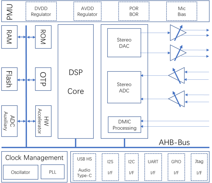
The SNC8600 integrates Cadence's high-performance HiFi3 DSP core up to 200 MHz, a 24-bit/192 Ksps high-standard stereo input and output codec, can connect 2 analog microphones and up to 10 digital microphones, provides 512 KB RAM and configurable Flash memory (default is 1 MB). Other peripheral circuits include support for a USB UAC2.0 controller, 3-way I2S, 2-way I2C, 1-way UART, and a set of GPIO, and an auxiliary ADC for key detection and analog sensor monitoring.
The SOUNDEC SDK software package provides complete device drivers, audio frameworks, sample programs, and custom template files. This document focuses on describing the various software modules, interfaces, functions and sample codes to help deepen the knowledge of the SOUNDEC SDK in audio applications.
# GPIO
# Function overview
The SNC8600 has a total of 17 general-purpose I/O (GPIO) pins. Eight of these pins are typically assigned to I2S, and the remaining six can be assigned different functions by configuring appropriate registers. Each GPIO pin can be configured as an internal pull-up/pull-down resistor, or set to high impedance. When configured as an input, the input value can be obtained by reading the register. The input can also be set as an edge trigger or level trigger to generate a CPU interrupt.
In short, the GPIO pins are bidirectional, non-inverting, and tri-state, with tri-state controlled input and output buffers.
The following table summarizes the pin positions and names of the general I/O of the SNC8600:
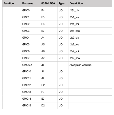
GPIO Pin Map
# GPIO usage
The use of GPIO is mainly to configure pin multiplexing and interrupt processing. The APIs involved are:
hal_gpio_set_pinmux_function: Sets the pin multiplexing function.
hal_gpio_set_direction: Sets the direction of the pin (input or output).
gpio_cfg_intr: Configures the interrupt.
gpio_enable_intr: Enables the interrupt.
# Sample code
The use of GPIO is relatively simple. A sample code can be found in the file app_gpio_test.c.
# I2S interface
# Function overview
The I2S interface module provides an interface for CODEC or DSP to connect to the APB bus. The 8600 uses the I2S interface to connect with other external digital audio devices, such as the drive amplifier, audio data transmission with the Bluetooth chip and i2s master control chip.
The I2S interface module has the following features:
32-bit APB bus width
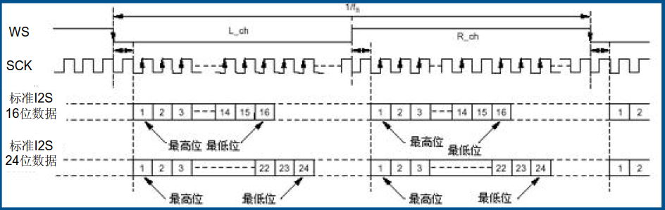
Support for Philips I2S protocol, support MSB, LSB alignment format
Support for 4-way I2S
Support for Master mode and Slave mode
Support for 12, 16, 20, 24, 32 bit audio data
External control of the sclk gating signal
FIFO depth of 16, with configurable trigger level
Built-in programmable DMA register
Support for TDM (SLAVE)
Support for sampling frequencies from 8K to 192K
Note:
For 32 frame length (wordsize), the sampling rate supported is 8K to 96K.
For 24 frame length (wordsize), the sampling rate supported is 8K to 192K, with an actual sampling rate of 193.5K.
For 16 frame length (wordsize), the sampling rate supported is 8K to 192K, with an actual sampling rate of 193.5K.
# Signal Timing
# API
The 8600 I2S has 4 channels, which can work in master or slave mode. For the purpose of this explanation, we will use one channel of I2S as an example.
# Initialization I2S_init()
hal_sysctrl_set_clock_gate(hal_sysctrl_get_clock_gate() | (1 << HAL_SYSCTRL_CLKGT_I2S1)); //config clock source
hal_gpio_set_pinmux_function(GPIO_0, 2);  //config GPIO multiplexed pins for I2S
......
i2s_cfg.mode 	 	 = I2S_MODE_MASTER;  //I2S parameters
i2s_cfg.standard	 = I2S_STANDARD_PHILIPS;
i2s_cfg.frameLength  = I2S_FRAMELENGTH_32B;
....
hal_i2s_init(I2S_INDEX_1, &i2s_cfg);  //init I2S1
i2s_it_start(I2S_INDEX_1, I2S1_IRQn, rxCB, txCB, i2s1_isr_handler); //enable I2S1
2
3
4
5
6
7
8
9
# Interrupt handling
The I2S interrupt handler is responsible for sending and receiving data. When the I2S sending FIFO is empty or the receiving FIFO is full, the I2S interrupt will be triggered. The interrupt handler will then be entered. In the interrupt handler, the data can be sent or the received data can be processed.
The following code shows an example of how to implement an I2S interrupt handler:
	void i2s_isr_status_handler(uint8_t i2sx)
{
......
	int32_t rxData[I2S_RX_FIFO_LEVEL*2] = {0};
	int32_t txData[I2S_TX_FIFO_LEVEL*2] = {0};
	if(hal_i2s_tx_ready(i2sx)) //EMPTY interrupt
	{
		if (i2sDevInfos[i2sx].isrCb[0])
			i2sDevInfos[i2sx].isrCb[0](i2sDevInfos[i2sx].txCbArg, &txData[0], &len,BIT_SLOT_32);//get data(with callback)to send
		hal_i2s_tx_data(i2sx, &txData[txCount]); //send data
	}
	if(hal_i2s_rx_ready(i2sx)) //FULL interrupt
	{
		if (i2sDevInfos[i2sx].isrCb[1])
			i2sDevInfos[i2sx].isrCb[1](i2sDevInfos[i2sx].rxCbArg, &rxData[0], &len,BIT_SLOT_32);// callback func to relay data to upper layer
	}
	//Other transit status handling....
}
2
3
4
5
6
7
8
9
10
11
12
13
14
15
16
17
18
# Set and Get
drv_status_t i2s_set_audio_freq(uint8_t i2sx, uint32_t audioFreq);
void i2s1_set_audio_freq(uint32_t audioFreq);
void i2s2_set_audio_freq(uint32_t audioFreq);
void i2s3_set_audio_freq(uint32_t audioFreq);
uint32_t i2s1_get_audio_freq(void);
uint32_t i2s2_get_audio_freq(void);
uint32_t i2s3_get_audio_freq(void);
drv_status_t i2s_tx_enable(uint8_t i2sx, uint8_t enable);
drv_status_t i2s_rx_enable(uint8_t i2sx, uint8_t enable);
drv_status_t i2s_set_mode(uint8_t i2sx, uint8_t mode);
drv_status_t i2s_set_format(uint8_t i2sx, uint8_t format);
drv_status_t i2s_set_sample_rate(uint8_t i2sx, uint32_t sampleRate);
drv_status_t i2s_set_word_length(uint8_t i2sx, uint8_t wordLength);
drv_status_t i2s_set_frame_length(uint8_t i2sx, uint8_t frameLength);
drv_status_t i2s_set_mute(uint8_t i2sx, uint8_t mute);
2
3
4
5
6
7
8
9
10
11
12
13
14
15
# I2C interface
# Function overview
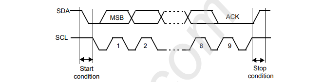
The I2C interface currently provided by the 8600 can be used as a master device to control the read and write data from other I2C slave devices, such as most digital sensors, or as a slave device to receive data from other I2C master devices, such as other host devices.
# Signal Timing grapoh
# API
Take the master interface as an example (The slave mode is similar).
# Initilization i2c_init()
void i2c_init(void)
{
    //config I2C clock signal
	uint32_t clkGate = hal_sysctrl_get_clock_gate();
	SETBIT(clkGate, HAL_SYSCTRL_CLKGT_I2C2);
	hal_sysctrl_set_clock_gate(clkGate);
	//config I2C parameters
	hal_i2c_disable(I2C_MASTER_SEL);
	hal_i2c_set_mode(I2C_MASTER_SEL, &i2cMasterCfg);
	hal_i2c_set_speed(I2C_MASTER_SEL, &i2cMasterCfg);
	hal_i2c_set_tx_fifo_level(I2C_MASTER_SEL, i2cMasterCfg.txFifo);
	hal_i2c_set_rx_fifo_level(I2C_MASTER_SEL, i2cMasterCfg.rxFifo);
    //config and enable I2C interrupt
	hal_i2c_set_intr_mask(I2C_MASTER_SEL, &i2cMasterCfg);
	hal_interrupt_register_isr_handler(I2C_MASTER_SEL_IRQ, i2c_master_isr);
	hal_interrupt_enable_irq(I2C_MASTER_SEL_IRQ);
}
2
3
4
5
6
7
8
9
10
11
12
13
14
15
16
17
18
# Data transmission
There are two ways to transmit data using I2C. The first way is to send and receive data in response to interrupts. The second way is to directly call the sending and receiving interface functions.
1)ISR i2c_master_isr(){
static void i2c_master_isr(void* arg)
{
    uint16_t stat = hal_i2c_get_intr_stat(I2C_MASTER_SEL); //get interrupt status
	if (stat & I2C_INTR_STAT_RX_UNDER) // receive data length error
	{
	    //retry I2C interface to read data
	}
	if(stat & I2C_INTR_STAT_STOP_DET) //I2C data transmission is finished
	{
	    //if there are data to be send
		call I2C Write to send data
		//if there is data to be read
		call I2C Read to receive data
	}
}
2
3
4
5
6
7
8
9
10
11
12
13
14
15
2)Interface to send data - i2c_master_write_bulk
//send I2C  slave device address
hal_i2c_update_tar_addr(i2cx, devAddr);
hal_i2c_write_data(i2cx, regAddr);
//send data
while(len)
{
	if((hal_i2c_get_status(i2cx)&I2C_STAT_TFNF))
	{
		hal_i2c_write_data(i2cx, buf[i]);
		i++;
		len--;
	}
}
2
3
4
5
6
7
8
9
10
11
12
13
14
3)interface to receive data - i2c_master_read_bulk{
while(len)
{
	uint8_t rx = hal_i2c_get_rx_fifo_len(i2cx);

	if(rx < 7 && cnt++ >= 100)
	{
		cnt = 0;
		//send slave device address for data reading
		hal_i2c_master_read_command(i2cx);
	}
	if(rx)
	{   //read data
		buf[i++] = hal_i2c_read_data(i2cx);
		len--;
	}
}
2
3
4
5
6
7
8
9
10
11
12
13
14
15
16
# UART interface
# Function overview
The SNC8600 provides a UART interface that can be used for serial port debugging or serial port communication with other external ICs. The UART interface has the following basic functions:
Full duplex operation: The UART interface can transmit and receive data simultaneously.
5-8 bit operation: The UART interface can transmit and receive characters that are 5 to 8 bits long.
Configurable parity: The UART interface can generate and detect parity bits. The parity can be even, odd, no parity, or fixed parity.
Configurable stop bits: The UART interface can generate and detect 1, 1.5, or 2 stop bits.
Break generation and detection functions: The UART interface can generate and detect break signals.
16 levels of depth (byte width) receive FIFO: The UART interface has a receive FIFO that can store up to 16 bytes of data. The FIFO has a configurable trigger level and timeout interrupt.
16 levels of depth (byte width) transmit FIFO: The UART interface has a transmit FIFO that can store up to 16 bytes of data. The FIFO has a configurable trigger level interrupt.
4-bit maskable interrupt source: The UART interface has 4 interrupt sources that can be masked individually. The interrupt priority can be configured.
Flexible baud rate configuration: The UART interface can be configured to operate at a wide range of baud rates.
# API
# Initialization
uart_init
//Config clock, baud rate, format, FIFO depth
void uart_init(void)
{

	uint32_t clkGate = hal_sysctrl_get_clock_gate();
	SETBIT(clkGate, HAL_SYSCTRL_CLKGT_UART);
	hal_sysctrl_set_clock_gate(clkGate);
	uart_cfg_t config;
	config.baudRate 	= UART_BUARD_RATE;
	config.dataLength   = UART_DATALENGRTH_8BIT;
	config.stopBits 	= UART_STOPBITS_1BIT;
	config.parityEnable = UART_PARITY_DISABLE;
	config.paritySelect = UART_PARITY_NO;			//UART_Parity_Even;
	config.breakControl = UART_BREAK_NORMAL;
	config.rxFifoLevel  = UART_R_FIFO_LEVEL_8B;	//UART_R_FIFO_Level_1B;
	config.txFifoLevel  = UART_T_FIFO_LEVEL_8B;	//UART_T_FIFO_Level_0B;
	config.inteConfig   = UART_ISR_ALL_DISABLE;
	hal_uart_init(&config);

}
2
3
4
5
6
7
8
9
10
11
12
13
14
15
16
17
18
19
# Data transmission
There are two ways to send and receive data. One is interrupting transmission, which is to send or receive data through callback after the hardware interrupt occurs. The other is ordinary transmission. By querying the hardware status bit, waiting for the hardware to be ready before send and receive data.
1)Interrupt transmission
Interrupt transmission requires the following steps:
Initialize the interrupt: This involves enabling the interrupt and configuring the interrupt controller.
Register the interrupt handler: This tells the interrupt controller which function to call when the interrupt occurs.
Register the callback function: This tells the interrupt handler which function to call when the interrupt is handled.
void uart_interrupt_init(void)
{
    hal_interrupt_register_isr_handler(UART_IRQn, uart_isr_handler);
    hal_interrupt_enable_irq(UART_IRQn);
    uart_register_callback(UART_TIMEOUT_CALLBACK_ID, timeout_callback);
}
2
3
4
5
6
Interrupt transmission
Register a send callback function and enable send interrupt
void uart_transmit_interrupt_config(uint8_t *txBuffer, uint16_t num)
{
	uart_queue_t *queue = uqueue;

	queue->head = queue->tail =  0;
	if(num > queue->size)
		num = queue->size;

	while(num)
	{
		queue->pdata[queue->tail] = *txBuffer;
		txBuffer++;
		queue->tail++;
		num--;
	}
	uart_register_callback(UART_TX_CALLBACK_ID, tx_callback);
	hal_uart_int_config(HAL_UART_IER_THREIENABLE_MASK,TURN_ON);//enable uart tx interrupt
}
2
3
4
5
6
7
8
9
10
11
12
13
14
15
16
17
18
Data is sent in the callback function.
void uart_transmit_interrupt(void)
{
	uart_queue_t *queue = uqueue;

	while(queue->head < queue->size)
	{
		if(hal_uart_get_status(UART_FLAG_TXE) == HAL_STATUS_OK)
		{
		    hal_uart_tx_data(queue->pdata[queue->head]);
		   	queue->head++;
		}
	}
}
2
3
4
5
6
7
8
9
10
11
12
13
Interrupt data receiving
Register receiving callback function and enable receiving interrupt
void uart_receive_interrupt_config(uint16_t num)
{
	uart_queue_t *queue = uqueue;

	queue->head = queue->tail =  0;
	queue->size = num;

	uart_register_callback(UART_RX_CALLBACK_ID, rx_callback);
	hal_uart_int_config(HAL_UART_IER_RDLIENABLE_MASK,TURN_ON);
}
2
3
4
5
6
7
8
9
10
Data is received in the callback function.
void uart_receive_interrupt(void)
{
	uart_queue_t *queue = uqueue;

	while(hal_uart_get_status(UART_FLAG_RXNE) == HAL_STATUS_OK && queue->tail < queue->size)
	{
		queue->pdata[queue->tail] = hal_uart_rx_data();
		queue->tail++;
	}
}
2
3
4
5
6
7
8
9
10
2)Normal send and receive
uart_tx_byte sends a single byte of data
uart_tx_array sends an array of bytes
uart_rx_byte receives a single byte of data
uart_rx_array receives an array of bytes
- ISR
Different callback processing functions can be called according to different flags.
static void uart_isr_handler(void *arg)
{
	SaveVectors(UART_IRQn);
	uint8_t stat = hal_uart_get_int_status();
	switch(stat)
	{
		case UART_LINE_STATUS:
			if(uart_callback[UART_RX_LINE_STATUS_CALLBACK_ID])
				uart_callback[UART_RX_LINE_STATUS_CALLBACK_ID]();
			hal_uart_int_config(HAL_UART_IER_RLSIENABLE_MASK,TURN_OFF);//disable receiver data status interrupt
			break;
		case UART_RX_FIFO_ISR:
			if(uart_callback[UART_RX_CALLBACK_ID])
				uart_callback[UART_RX_CALLBACK_ID]();
			break;
		case UART_TX_FIFO_ISR:
			if(uart_callback[UART_TX_CALLBACK_ID])
				uart_callback[UART_TX_CALLBACK_ID]();
			hal_uart_int_config(HAL_UART_IER_THREIENABLE_MASK,TURN_OFF);//diable tx fifo interrupt
			break;
		case UART_RX_TIMEOUT:
			if(uart_callback[UART_TIMEOUT_CALLBACK_ID])
				uart_callback[UART_TIMEOUT_CALLBACK_ID]();
			 break;
		case UART_MODEM_STATUS:
			if(uart_callback[UART_MODEM_CALLBACK_ID])
				uart_callback[UART_MODEM_CALLBACK_ID]();
			hal_uart_int_config(HAL_UART_IER_MSTENABLE_MASK,TURN_OFF);//disable modem status change interrupt
			 break;
		default:
			break;
	}
	RestoreVectors(UART_IRQn);
}
2
3
4
5
6
7
8
9
10
11
12
13
14
15
16
17
18
19
20
21
22
23
24
25
26
27
28
29
30
31
32
33
34
# Sample code
Please refer to app_uart_test.c
# CODEC(ADC/DAC)
# Function overview
The SNC8600 supports the following CODEC features:
Dual stereo 24-bit ADC with a dynamic range of up to 106dB.
Dual stereo 24-bit DAC with a dynamic range of up to 110dB.
Sampling rates supported by ADC/DAC: 8k, 16k, 32k, 44.1k, 48k, 88.2k, 96k, 176.4k, and 192k.
Up to 10 digital microphones.
ADC supports Fast and Slow mode, with the latter retaining higher accuracy.
ADC/DAC supports Master or Slave mode.
Low power voice detection.
Support for wind noise detection, AGC, DRC, mixing, and other processing.
# ADC Interface
# Parameter configuration
1)Data Struct for configuring parameters
typedef struct {
	hal_codec_ai_mode_t master_slave;			/* Master or slave mode */
	uint32_t sample_rate;						/* ADC12 sample rate */

	hal_codec_channel_sel_t aiadc1_sel;			/* Mixer channel 1 output selection on ADC path, 0:ADC1, 1:ADC2, 2:(ADC1+ADC2)/2, 3:None */
	hal_codec_channel_sel_t aiadc2_sel;			/* Mixer channel 2 output selection on ADC path, 0:ADC2, 1:ADC1, 2:(ADC1+ADC2)/2, 3:None */
	hal_codec_adc_mixer_mode_t mix_rec;			/* ADC12 mixed with DAC or not */
	hal_codec_adc12_power_mode_t adc12_mode;	/* ADC1 and ADC2 power mode, 0: Normal mode, 1: Low power mode */
	hal_codec_wnf_mode_t wnf;					/* ADC12 wind noise filter */

	bool	agc_enable;							/* ADC12 AGC Enable or not */
	bool	hpf_enable;							/* ADC12 HPF Enable or not */
	bool 	is_amic;							/* Indicates whether it's analog microphone or not; true:analog microphone; false:digital microphone. */

	/* ADC12 can be as either analog microphone or digital microphone */
	codec_amic12_config_t amic;					/* Analog microphone specified config */
	codec_dmic12_config_t dmic;					/* Digital microphone specified config */

	hal_codec_adc_agc_config_t *agc_config;		/* ADC12 AGC configuration information */
} codec_adc12_config_t;
2
3
4
5
6
7
8
9
10
11
12
13
14
15
16
17
18
19
20
2)Interface for configuration -codec_config_adc12(codec_adc12_config_t *config){
//If the ADC is configured as a Digital Microphone Interface (DMIC), it is necessary to configure the multiplexed PIN pin for clock and data input.
if (!config->is_amic)
{
	hal_gpio_set_pinmux_function(GPIO_8, GPIO_8_FUNC_DMIC_CLK11);
	hal_gpio_set_pinmux_function(GPIO_9, GPIO_9_FUNC_DMIC_IN1);
}
2
3
4
5
// Configure parallel data reading, sampling rate and master/slave mode
hal_codec_set_adc12_audioif_parallel();
hal_codec_set_adc12_master_slave_mode(config->master_slave);
hal_codec_set_adc12_sample_rate(codec_samplerate_transform(config->sample_rate));
2
3
configure ADC for two digital output channels, and whether to mix the ADC output with the DAC output.
hal_codec_select_adc1_output(config->aiadc1_sel);
hal_codec_select_adc2_output(config->aiadc2_sel);
hal_codec_select_adc12_mixer_mode(config->mix_rec);
hal_codec_set_adc12_power_mode(config->adc12_mode);
2
3
4
//Depending on whether the ADC is configured as an Analog Microphone Interface (AMIC) or a Digital Microphone Interface (DMIC), further configuration may be required.
if (config->is_amic) //Analog Microphone
{
	hal_codec_disable_pga_lf_drift();
	hal_codec_set_amic1_capcouple(config->amic.capcouple1);
	hal_codec_set_amic2_capcouple(config->amic.capcouple2);

	hal_codec_select_adc1_data_provided(HAL_CODEC_ADC_DATA_PROVIEDE_ANALOG_ADC);
	hal_codec_select_adc2_data_provided(HAL_CODEC_ADC_DATA_PROVIEDE_ANALOG_ADC);
	if (config->adc12_mode == HAL_CODEC_ADC12_NORMAL_MODE) {
		hal_codec_set_dmic12_clock(HAL_CODEC_DMIC_RATIO_12);
	} else {
		hal_codec_set_dmic12_clock(HAL_CODEC_DMIC_RATIO_4);
	}

	hal_codec_set_amic1_input_mode(config->amic.micdiff1);
	hal_codec_set_amic1_analog_gain(config->amic.gim1);
	hal_codec_set_adc1_digital_gain(config->amic.gid1);

	hal_codec_set_amic2_input_mode(config->amic.micdiff2);
	hal_codec_set_amic2_analog_gain(config->amic.gim2);
	hal_codec_set_adc2_digital_gain(config->amic.gid2);

	hal_codec_set_amic1_bias_state_in_power_down(config->amic.micbias1_v);
	hal_codec_set_amic2_bias_state_in_power_down(config->amic.micbias2_v);
}
else //Digital Microphone
{
	hal_codec_set_dmic12_clock(config->dmic.clock);
	hal_codec_set_adc1_digital_gain(config->dmic.gid1);
	hal_codec_set_adc2_digital_gain(config->dmic.gid2);
	hal_codec_select_adc1_data_provided(config->dmic.adc_dmic_sel1);
	hal_codec_select_adc2_data_provided(config->dmic.adc_dmic_sel2);
}
2
3
4
5
6
7
8
9
10
11
12
13
14
15
16
17
18
19
20
21
22
23
24
25
26
27
28
29
30
31
32
33
- Initialization
codec_adc12_init(void)
//Configure interrupts, fifo, etc., and enable ADC
codec_adc12_config_t *config = &g_adc12_config;

codec_register_cb(CODEC_CALLBACK_ADC, app_codec_adc_callback);
codec_config_adc12(config);
hal_codec_fifo_init(HAL_CODEC_FIFO_ADC12, CODEC_FIFO_AF_LEVEL);
#if !CODEC_USE_ONE_IRQ
hal_codec_unmask_interrupt(CODEC_ADC_INT_CHANNEL, CODEC_ADC_INT_SRC);	//Unmask a FIFO interrupt
#endif
codec_adc12_start();
2
3
4
5
6
7
8
9
# ISR
codec_adc_isr_handler(Retrieve converted data)
// If the Analog-to-Digital Converter (ADC) has finished converting an
analog signal to a digital value, read the converted value according to
the number of bits that were used to represent the value.
if (hal_codec_get_interrupt_status(CODEC_ADC_INT_CHANNEL) & (1 << CODEC_ADC_INT_SRC))
{
    if(hal_codec_get_adc_data_mode() == CODEC_ADC_DATA_MODE_16BIT)
	{
#if CODEC_ADC12_ENABLE
		hal_codec_read_adc12_data_16bit(&adcData[0]);
#endif
    }else
	{
#if CODEC_ADC12_ENABLE
		hal_codec_read_adc12_data_24bit(&adcData[0], &adcData[1]);
#endif
    }
}
// The data is passed to the next layer for further processing.
2
3
4
5
6
7
8
9
10
11
12
13
14
15
16
17
18
19
# Other interfaces(Set/Get)
drv_status_t codec_enable_adc12_hpf(uint8_t enable);
drv_status_t codec_select_adc12_mixer_mode(uint8_t enable);
drv_status_t codec_set_adc1_aiadc(uint8_t sel);
drv_status_t codec_set_adc2_aiadc(uint8_t sel);
drv_status_t codec_set_adc12_wnf_mode(uint8_t mode);
drv_status_t codec_adc12_agc_enable(uint8_t enable);
drv_status_t codec_set_adc12_agc_stereo(uint8_t enable);
drv_status_t codec_set_adc12_agc_target(uint8_t target);
drv_status_t codec_adc12_agc_noise_gate_enable(uint8_t enable);
drv_status_t codec_set_adc12_agc_noise_gate_thres(uint8_t threshold);
drv_status_t codec_adc12_agc_snr_optimzation(uint8_t enable);
drv_status_t codec_set_adc12_agc_hold_time(uint8_t holdTime);
drv_status_t codec_set_adc12_agc_attack_time(uint8_t attackTime);
drv_status_t codec_set_adc12_agc_decay_time(uint8_t decayTime);
drv_status_t codec_set_adc12_agc_min_gain(uint8_t gain);
drv_status_t codec_set_adc12_agc_max_gain(uint8_t gain);
drv_status_t codec_adc12_enable(uint8_t enable, auChannel_t lr);
drv_status_t codec_set_adc12_gain(int8_t gain, uint8_t isAgain, auChannel_t lr);
void codec_adc12_aias(float s, int32_t dir);
void codec_tune_adc_sample_rate(uint32_t dataLen, uint32_t fifoSize);
2
3
4
5
6
7
8
9
10
11
12
13
14
15
16
17
18
19
20
# DAC interfaces
# Parameter configuration
The interface to configure the DAC is called codec_config_dac(). The configuration parameters are stored in a data structure, which is defined as follows:
codec_dac_config_t g_dac_config = {
	.master_slave 			= CODEC_DEFAULT_MODE,
	.sample_rate 			= CONFIG_CODEC_FREQUENCY,
	.is_hp					= true,
	.drc_enable				= false,
	.left_only 				= false,

	.aidacl_sel 			= HAL_CODEC_CHANNEL_SEL_NORMAL_INPUTS,
	.aidacr_sel				= HAL_CODEC_CHANNEL_SEL_NORMAL_INPUTS,
	.dac_mix				= HAL_CODEC_PLAYBACK_DAC_ONLY,
	.mixdacl_sel			= HAL_CODEC_CHANNEL_SEL_NORMAL_INPUTS,
	.mixdacr_sel			= HAL_CODEC_CHANNEL_SEL_NORMAL_INPUTS,
	.mixadc1_sel			= HAL_CODEC_CHANNEL_SEL_NORMAL_INPUTS,
	.mixadc2_sel			= HAL_CODEC_CHANNEL_SEL_NORMAL_INPUTS,

	.godl					= 0,
	.godr					= 0,
	.gomixl					= 0,
	.gomixr					= 0,
	.gimixl					= 0,
	.gimixr					= 0,

	.lthres					= 0,
	.rthres					= 0,
	.lcomp					= HAL_CODEC_DRC_RATE_1,
	.rcomp					= HAL_CODEC_DRC_RATE_1,

	.hp_sel					= 0,
#ifdef SUPPORT_SPEAKER_EQ
	.gol					= 5,
	.gor					= 5,
#else
	.gol					= 0,
	.gor					= 0,
#endif
};
2
3
4
5
6
7
8
9
10
11
12
13
14
15
16
17
18
19
20
21
22
23
24
25
26
27
28
29
30
31
32
33
34
35
36
37
# Initialization - codec_dac_init()
// Enable interrupts, FIFO, etc., and start the DAC
codec_config_dac(&g_dac_config);
hal_codec_fifo_init(HAL_CODEC_FIFO_DAC, CODEC_FIFO_AE_LEVEL);
#if CODEC_USE_ONE_IRQ
hal_codec_unmask_interrupt(CODEC_INT_CHANNEL, CODEC_INT_SRC);	//Unmask a FIFO interrupt
#else
hal_codec_unmask_interrupt(CODEC_DAC_INT_CHANNEL, CODEC_DAC_INT_SRC);	//Unmask a FIFO interrupt
#endif
codec_dac_start();
codec_register_cb(CODEC_CALLBACK_DAC, app_codec_dac_callback);
2
3
4
5
6
7
8
9
10
- ISR
codec_dac_isr_handler (Send data that need to be converted during interrupt processing)
SaveVectors(CODEC_DAC_IRQ);
hal_interrupt_clear_irq(CODEC_DAC_IRQ);
// If the interrupt signal indicates that the data conversion is ready
to start, send the data then
if (hal_codec_get_interrupt_status(CODEC_DAC_INT_CHANNEL) & (1 << CODEC_DAC_INT_SRC))
{
	if (g_codec_cb_table[CODEC_CALLBACK_DAC])
		g_codec_cb_table[CODEC_CALLBACK_DAC](&dil, &dir);
    //data to be converted is stored in dil and dir(strereo left and right channels)
	hal_codec_write_dac_data(dil, dir);

	hal_codec_clear_interrupt(CODEC_DAC_INT_CHANNEL, CODEC_DAC_INT_SRC);
}
RestoreVectors(CODEC_DAC_IRQ);
2
3
4
5
6
7
8
9
10
11
12
13
14
15
# Other DAC interfaces
drv_status_t codec_dac_drc_enbale(uint8_t enable);
drv_status_t codec_set_dac_drc_lthres(uint8_t threshold);
drv_status_t codec_set_dac_drc_rthres(uint8_t threshold);
drv_status_t codec_set_dac_drc_lcomprate(uint8_t comprate);
drv_status_t codec_set_dac_drc_rcomprate(uint8_t comprate);
drv_status_t codec_dac_enable(uint8_t enable);
drv_status_t codec_dac_mix_enable(uint8_t enable);
drv_status_t codec_set_dac_golmix_gain(uint8_t gain);
drv_status_t codec_set_dac_gormix_gain(uint8_t gain);
drv_status_t codec_set_dac_gilmix_gain(uint8_t gain);
drv_status_t codec_set_dac_girmix_gain(uint8_t gain);
drv_status_t codec_set_dac_mixdacl(uint8_t sel);
drv_status_t codec_set_dac_mixdacr(uint8_t sel);
drv_status_t codec_set_dac_aidacl(uint8_t sel);
drv_status_t codec_set_dac_aidacr(uint8_t sel);
drv_status_t codec_select_dac_mixadc1_input(uint8_t sel);
drv_status_t codec_select_dac_mixadc2_input(uint8_t sel);
2
3
4
5
6
7
8
9
10
11
12
13
14
15
16
17
# USB UAC
# Overview
The SNC8600 USB driver implements the following features of UAC2.0 and UAC1.0:
USB device descriptor management
Configuration device descriptor management
Audio Control request: SET_CUR and GET_CUR
Audio feature unit
Audio synchronization type: asynchronous and feedback.
Audio Class-Specific AC Interfaces
Audio Class-Specific AS Interfaces
Adaptive UAC2.0&UAC1.0
Supports sample rates from 8k to 192k
Audio data transmission is carried out through Isochronous Endpoint. Audio control requests are managed through Control Endpoint (Endpoint 0). Audio quality depends on the synchronization mechanism of the data transmission. The SNC8600 USB Driver supports two synchronization mechanisms: synchronization through SOF Packet and the Feedback mechanism of UAC2.0.
The SNC8600 uses DMA transmission and multi-buffer storage to prevent data overwrite. DMA transmission is a method of transferring data directly from the device to the memory without the intervention of the CPU.
The USB Driver also supports basic audio control requests, such as setting the volume and mute.
For UAC1.0, SNC8600 supports all the audio control requests except SET_MEM and GET_MEM.
For UAC2.0, SNC8600 only supports REQ_CUR and REQ_RANGE.
# UAC core data structures
# UAC configuration descriptor
Please refer to the struct uac_CfgDesc in usb_descriptor.h
# UAC class
The audio interface is responsible for sending and receiving audio data, as well as handling control requests from the host. It is loaded when the USB protocol stack is initialized, which is usually done when the device is first turned on.
usb_dev_class_cb_t usbDevComposite[USB_FUN_MAX_NUM_INTERFACES] =
{
    {
        uac_init,
        uac_de_init,
        uac_setup,
        uac_ep0_tx_ready,
        uac_ep0_rx_ready,
        NULL,
        NULL,
        uac_sof,
        NULL,
        NULL,
        uac_get_cfg_desc,
        uac_get_cfg_desc,
        uac_get_cfg_desc,
        uac_get_device_qualifier_desc,
    },

    #if SUPPORT_USB_SPK
    {
        uac_init,
        uac_de_init,
        NULL,
        NULL,
        NULL,
        uac_feedback,
        uac_data_out,
        NULL,
        uac_iso_in_incomplete,
        uac_iso_out_incomplete,
        NULL,
        NULL,
        NULL,
        NULL,
    },
    #endif

    #if SUPPORT_USB_MIC
    {
        NULL,
        NULL,
        NULL,
        NULL,
        NULL,
        uac_mic_in,
        NULL, /*EP0_TxSent*/
        NULL, /*SOF */
        NULL,
        NULL,
        NULL,
        NULL,
        NULL,
        NULL,
    },

    #endif
    #if SUPPORT_USB_HID
    {
        usb_dev_hid_init,
        usb_dev_hid_de_init,
        NULL,
        NULL, /*EP0_TxSent*/
        usb_dev_hid_ep0_rx_ready,
        usb_dev_hid_data_in,
        usb_dev_hid_data_out,
        NULL, /*SOF */
        NULL,
        NULL,
        NULL,
        NULL,
        NULL,
        NULL,
    }

    #endif
};
2
3
4
5
6
7
8
9
10
11
12
13
14
15
16
17
18
19
20
21
22
23
24
25
26
27
28
29
30
31
32
33
34
35
36
37
38
39
40
41
42
43
44
45
46
47
48
49
50
51
52
53
54
55
56
57
58
59
60
61
62
63
64
65
66
67
68
69
70
71
72
73
74
75
76
77
# Audio device interface
usb_audio_interface_t uac_fops =
{
    Audio_Init,
    Audio_DeInit,
    Audio_PlaybackCmd,
    Audio_VolumeCtl,
    Audio_MuteCtl,
    Audio_PeriodicTC,
    Audio_GetState,
};
2
3
4
5
6
7
8
9
10
This audio interface controls the underlying audio device and provides basic audio controls, such as mute and volume control. It is loaded via the uac_register_interface() function during USB initialization.
# How to use UAC
1)define device descriptor, (refer to usb_decriptor.h)
2)call these functions in usb_init(),
/* Add Supported Class */
usb_dev_register_class(&gUsbDevice, usbDevComposite);
/* Add Interface callbacks for AUDIO Class */
uac_register_interface(&gUsbDevice, &uac_fops);
/* Start Device Process */
usb_dev_start(&gUsbDevice);
hal_interrupt_enable_irq(USB_IRQn);
2
3
4
5
6
7
3)data transfer
uac_data_out -- receives audio data from the USB and stores it in the receive FIFO.
uac_mic_in -- sends audio data from the send FIFO to the USB.
4)audio control requests
The USBD_AUDIO_Setup() and USBD_AUDIO_EP0_RxReady() functions handle control requests from the host. These functions eventually call the underlying uac_fops functions to complete the control request.
# USB HID
# Function overview
The SNC8600 supports Human Interface Device (HID) communication that complies with the Class v1.11 specification. This allows for two-way communication, which can be used in USB audio applications to achieve volume control, playback pause, resume, and other functions. It can also be used to the transmission of HID customized messages. All communications are based on interrupt transmission mode, and the maximum size of a HID data packet that can be sent is 64 bytes. Data packets larger than this size need to be processed using sub-packetization.
# Core data structures
# HID descriptor
Descriptor is defined in uac_CfgDesc.h
#if SUPPORT_USB_HID
	DESC_SIZE_INTF,                             /* Size of this descriptor in bytes */
	DESC_TYPE_INTF,	                             /* INTERFACE Descriptor Type */
	INTF_HID,                            /* Number of this interface. */
	0x00U,							                             /* Value used to select this alternate setting for the interface identified in the prior field */
	USB_HID_KEYBOARD_ENDPOINT_COUNT,                             /* Number of endpoints used by this interface (excluding endpoint zero). */
	HID_CLASS, 		                             /* Class code (assigned by the USB-IF). */
	0x00U,		                             					 /* Subclass code (assigned by the USB-IF). */
	0X00U,		                             					 /* Protocol code (assigned by the USB). */
	0x00U,							                             /* Index of string descriptor describing this interface */

	DESC_SIZE_HID,		                             /* Numeric expression that is the total size of the HID descriptor. */
	DESC_TYPE_HID,		                             /* Constant name specifying type of HID descriptor. */
	0x11U, 0x01U,					                             /* Numeric expression identifying the HID Class Specification release. */
	0x00U,							                             /* Numeric expression identifying country code of the localized hardware */
	0x01U,							                             /* Numeric expression specifying the number of class descriptors(at least one report descriptor) */
	DESC_TYPE_HID_REPORT,                              /* Constant name identifying type of class descriptor. */
	USB_SHORT_GET_LOW(DESC_SIZE_HID_KEYBOARD_REPORT),/* Numeric expression that is the total size of the Report descriptor. */
	USB_SHORT_GET_HIGH(DESC_SIZE_HID_KEYBOARD_REPORT),

	/*OUT*/
	0x07, 							 		 					  /* Size of this descriptor in bytes */
	DESC_TYPE_EP,								  /* endpoint Descriptor Type */
	AUDIO_HID_OUT_EP,					                          /* The address of the endpoint on the USB device described by this descriptor. */
	EP_TYPE_INTR, 									  /* This field describes the endpoint's attributes */
	0x40,														  /* Maximum packet size this endpoint is capable of sending or receiving when this configuration is selected. */
	0x00,
	0x20,												           /* Interval for polling endpoint for data transfers. */
	/*HID KEY IN*/
	DESC_SIZE_EP,                               /* Size of this descriptor in bytes */
	DESC_TYPE_EP,	                              /* endpoint Descriptor Type */
	AUDIO_HID_IN_EP,
	/* The address of the endpoint on the USB device described by this descriptor. */
	EP_TYPE_INTR,                                       /* This field describes the endpoint's attributes */
	0x40,                                                         /* Maximum packet size this endpoint is capable of sending or receiving when this configuration is selected. */
	0x00,
	0x04,                                                        /* Interval for polling endpoint for data transfers. */
#endif
uint8_t g_UsbDeviceHidKeyboardReportDescriptor[HID_KEYBOARD_DESC_SIZE] =
{
	0x05, 0x0C, // Usage Page (Consumer)
	0x09, 0x01, // Usage(Consumer Control)
	0xA1, 0x01, // Collection(Application )
	/***************************************************/
	0x85, 0x01,
	0x09, 0x04,
	0x15, 0x00,
	0x26, 0xFF, 0x00,
	0x75, 0x08,
	0x95, 0x3F,
	0x91, 0x82,
	/***************************************************/
	0x85, 0x01,
	0x15, 0x00, // Logical Minimum(0x0 )
	0x26, 0xFF, 0x00,
	//0x25, 0x01, // Logical Maximum(0x1 )
	0x75, 0x01, // Report Size(0x1 )
	0x95, 0x01, // Report Count(0x5 )

	0x09, 0xE9, // Usage(Volume Increment)
	0x81, 0x02,

	0x09, 0xEA, // Usage(Volume Decrement)
	0x81, 0x02, // Input(Data, Variable, Absolute, No Wrap, Linear, Preferred State, No Null Position, Bit Field)

	0x09, 0xCD, // Usage(Play/Pause)
	0x81, 0x02,

	0x09, 0xB5, // Usage(Scan Next Track)
	0x81, 0x02,

	0x09, 0xB6, // Usage(Scan Previous Track)
	0x81, 0x02,

	0x09, 0xB7, // Usage(Stop)
	0x81, 0x02,

	0x09, 0xB3, // Usage(Fast Forward)
	0x81, 0x02,

	0x09, 0xB4, // Usage(Rewind)
	0x81, 0x02, // Input(Data, Variable, Absolute, No Wrap, Linear, Preferred State, No Null Position, Bit Field)

	0x05, 0x0B,
	0x09, 0x24,
	0x81, 0x02,

	0x09, 0x20,
	0x81, 0x02, // Input(Data, Variable, Absolute, No Wrap, Linear, Preferred State, No Null Position, Bit Field)

	0x09, 0x2F,
	0x81, 0x06,
	0x95, 0x05, // Report Count(0x5 )
	0x81, 0x01,

	0x85, 0x02,
	0x09, 0x03,
	0x15, 0x00,
	0x26, 0xFF, 0x00,
	0x75, 0x08,
	0x95, 0x3F,
	0x81, 0x02,

	0xC0
};
2
3
4
5
6
7
8
9
10
11
12
13
14
15
16
17
18
19
20
21
22
23
24
25
26
27
28
29
30
31
32
33
34
35
36
37
38
39
40
41
42
43
44
45
46
47
48
49
50
51
52
53
54
55
56
57
58
59
60
61
62
63
64
65
66
67
68
69
70
71
72
73
74
75
76
77
78
79
80
81
82
83
84
85
86
87
88
89
90
91
92
93
94
95
96
97
98
99
100
101
102
103
104
105
# HID class interface
The HID interface includes the initialization of the HID class and the message transmission. When initializing the USB protocol stack, it is loaded together with the UAC class through the usb_dev_register_class() function.
{
	usb_dev_hid_init,
	usb_dev_hid_de_init,
	NULL,
	NULL, /*EP0_TxSent*/
	usb_dev_hid_ep0_rx_ready,
	usb_dev_hid_data_in,
	usb_dev_hid_data_out,
	NULL, /*SOF */
	NULL,
	NULL,
	NULL,
	NULL,
	NULL,
	NULL,
}
2
3
4
5
6
7
8
9
10
11
12
13
14
15
16
The reception of HID data is processed in the usb_dev_hid_data_out and transmission of HID data is processed in the usb_dev_hid_data_in
# How to use HID
Similar with UAC,please refer to section 7.4.