# Soundec Playground Evaluation Suite User Manual
Hardware and Software Evaluation tool for SNC8x series professional audio processor (integrated AI algorithms and high-quality Codec, high-performance DSP, high-speed USB, and PMU)
# Part List
Soundec Playground Evaluation Board
SNC8600 Core Board
2 * USB-A to USB-C cables
Adaptor Boards
# Documents
Soundec Playground Evaluation Suite User Manual
# Typical Applications
Noise Cancellation Headset、USB Headset, Audio Monitor (opens new window)
Audio front-end process
Multimedia player
Instrumental audio effects
In-car audio system
# Evalation Board
The Soundec Playground evaluation board provides all necessary analog/digital input and output interfaces for the SNC8x series professional audio processors. Users can easily communicate and debug with Tensilica HiFi3 DSP through the built-in USB to serial controller of the evaluation board or the standard JTAG controller. The SNC8x series professional audio processor can be customized and developed based on the SDK, and can also be debugged without coding.
The Soundec Playground evaluation board supports a series of adaptor boards to achieve various audio services, and personalized hardware configurations can be added through the universal board to quickly complete product prototype construction. Simply connect to a simple USB 5V power supply, and all other onboard voltages are provided by the Soundec Playground evaluation board. PCBA adopts a four layer board design, which includes a grounding layer and a power supply layer. The core clock is provided by the onboard 24MHz crystal oscillator.
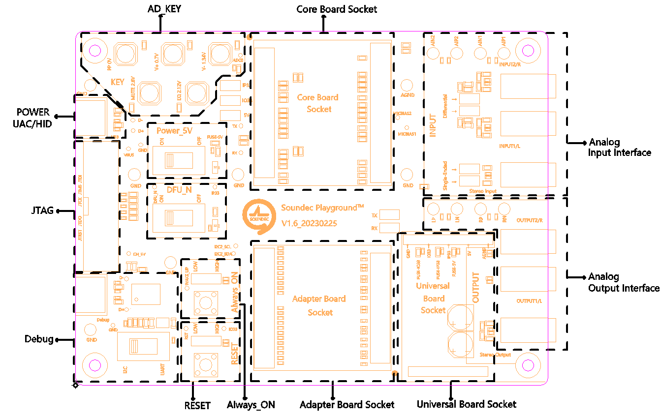
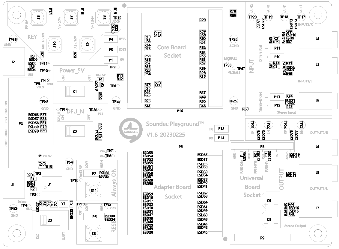
# Layout
The following picture shows the layout of the evaluation board
# Preparation
# Download and Install "Soundec Studio"
Soundec provides a supporting software for the evaluation suite, Soundec Studio. Please follow the steps below to download and install:
Dowload Soundec Studio (opens new window), Save to computer. Uncompress zip file and run "SoundecStudio.exe".
# Default settings for switches and jumpers
The following table lists the default settings for switches and jumpers on the evaluation board:
| Jumper and Switch Connections | Option Selected |
|---|---|
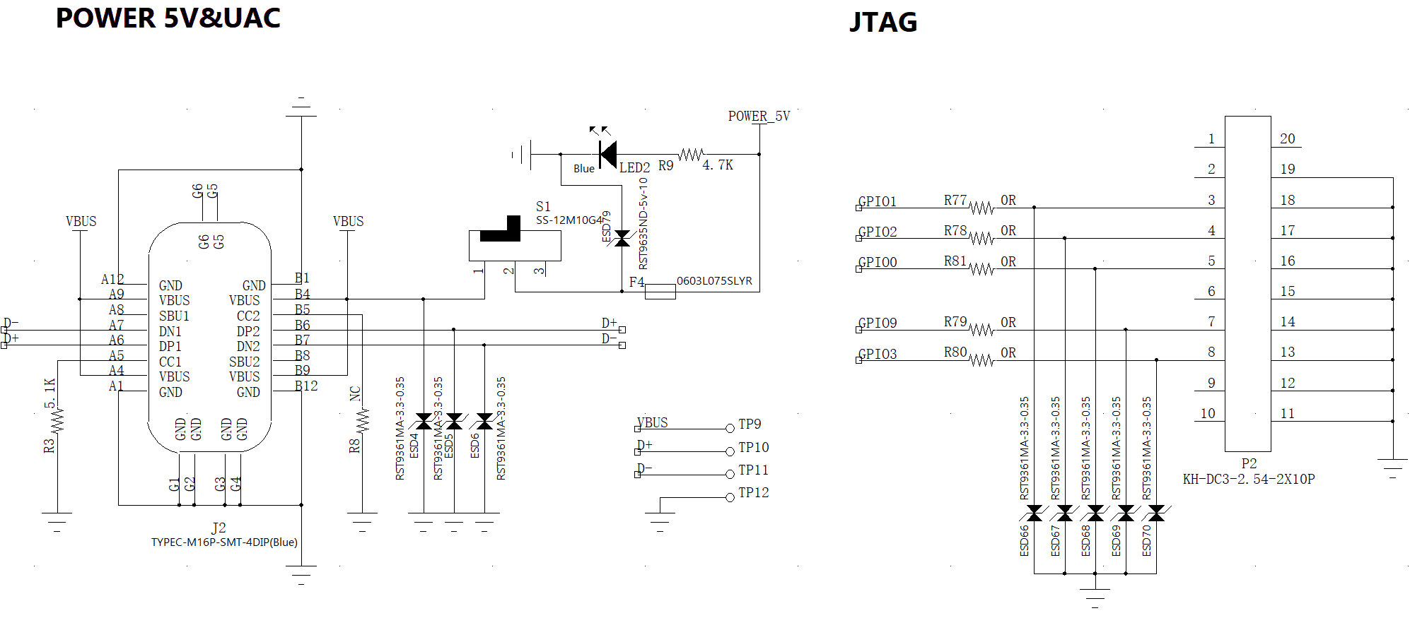
| S1 ON | USB provides 5V power |
| P1 ON | USB provides 5V power |
| P4 ON | Enable IP33 VOUT |
| P5 ON | Enable IO33 VOUT |
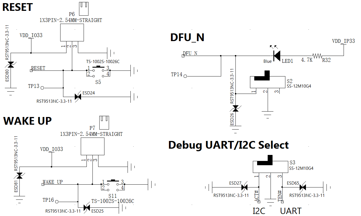
| P6 ON | RESET pin pulled up by IO33 |
| S2 OFF | Turn off DFU |
| S3 UART | Turn on Debug |
Before using the evaluation board for the first time, please confirm that the switch and jumper settings are consistent with the above table.
# Begin to Use
# Power
J2 is the power supply interface of the evaluation board. This is a USB-C female interface, and it is recommended to use a 5V/1A power supply.
# Control Port
J2 is also the control port of the evaluation board. After installing Soundec Studio on the computer, please use a USB cable to connect, run Soundec Studio, and follow the prompts.
# Audio Codec Interfaces
# Audio Input and Output
Soundec Playground has multiple audio input and output options, including digital and analog. There are three analog inputs, three analog output, up to ten digital microphone channels, and up to three serial audio interface ports.
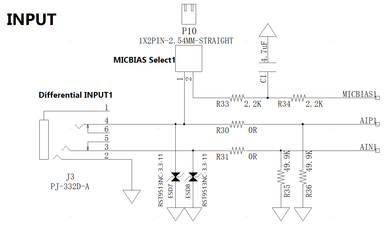
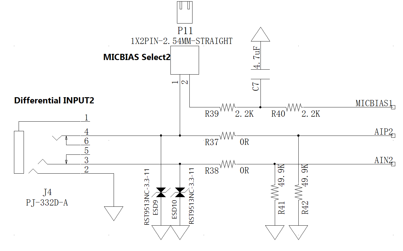
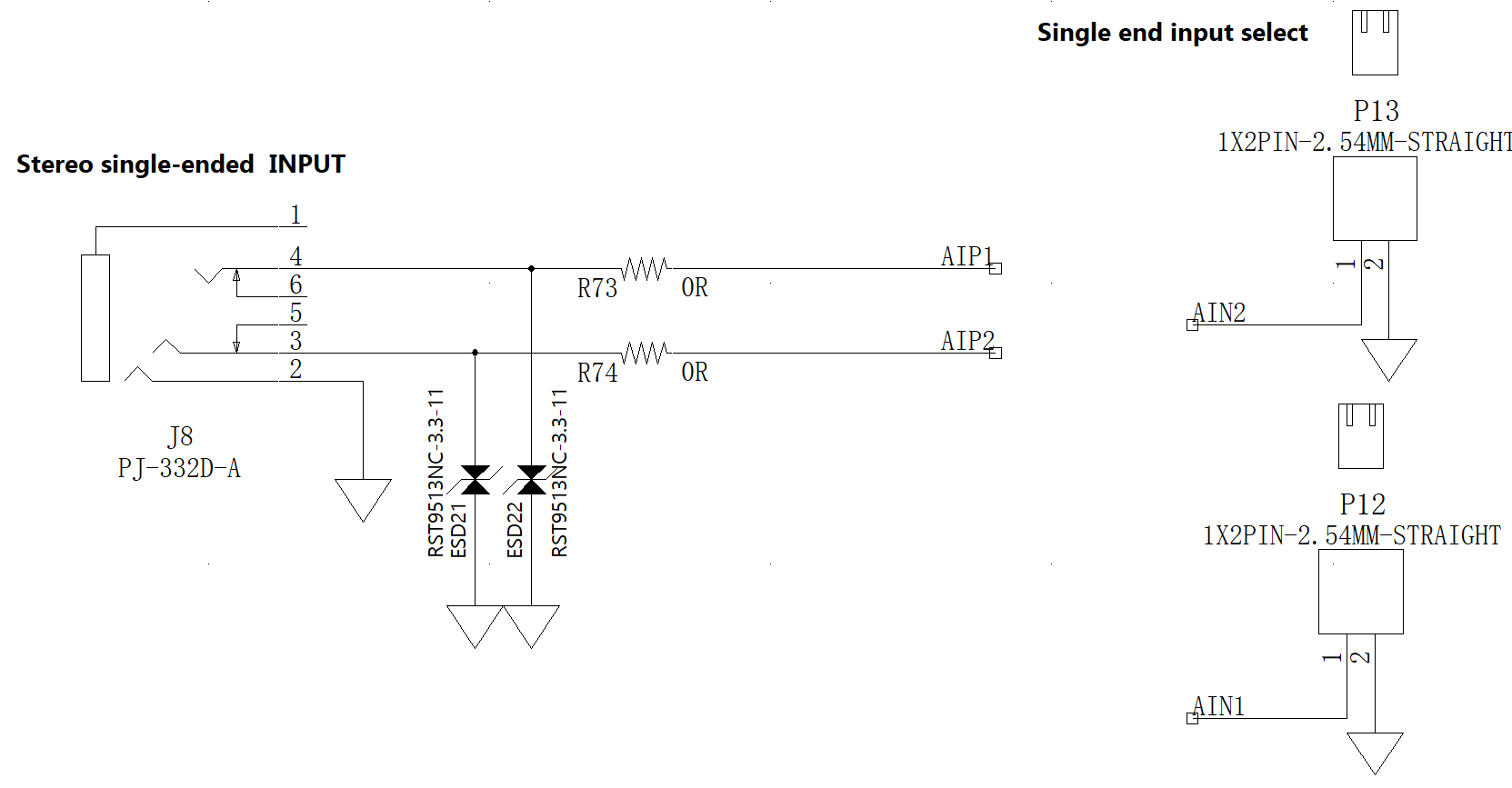
# Analog Audio Input
The evaluation board provides two types of analog inputs: a single ended stereo headphone interface (J8) and a dual Line In differential interface (J3 and J4). Each analog input supports programmable analog gain amplifiers.
Please refer to the table below for the selection of analog input signals.
| ADC channel | Jumper | Audio Input |
|---|---|---|
| ADC1 | P10 on,P12 on | Single-end |
| ADC1 | P10 off,P12 off | Differential-end |
| ADC2 | P11 on,P13 on | Single-end |
| ADC2 | P11 off,P13 off | Differential-end |
Notes:
Single-end input ports and differential-end input ports cannot be used simultaneously.
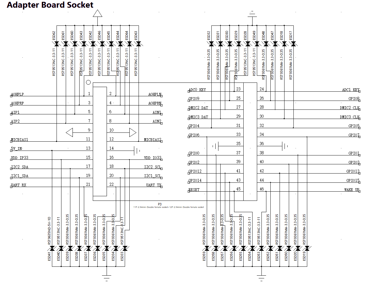
Analog input can also be connected to the input of adapter board through the P3. When the audio input is connected to adapter board, the audio input port on the evaluation board cannot be used.
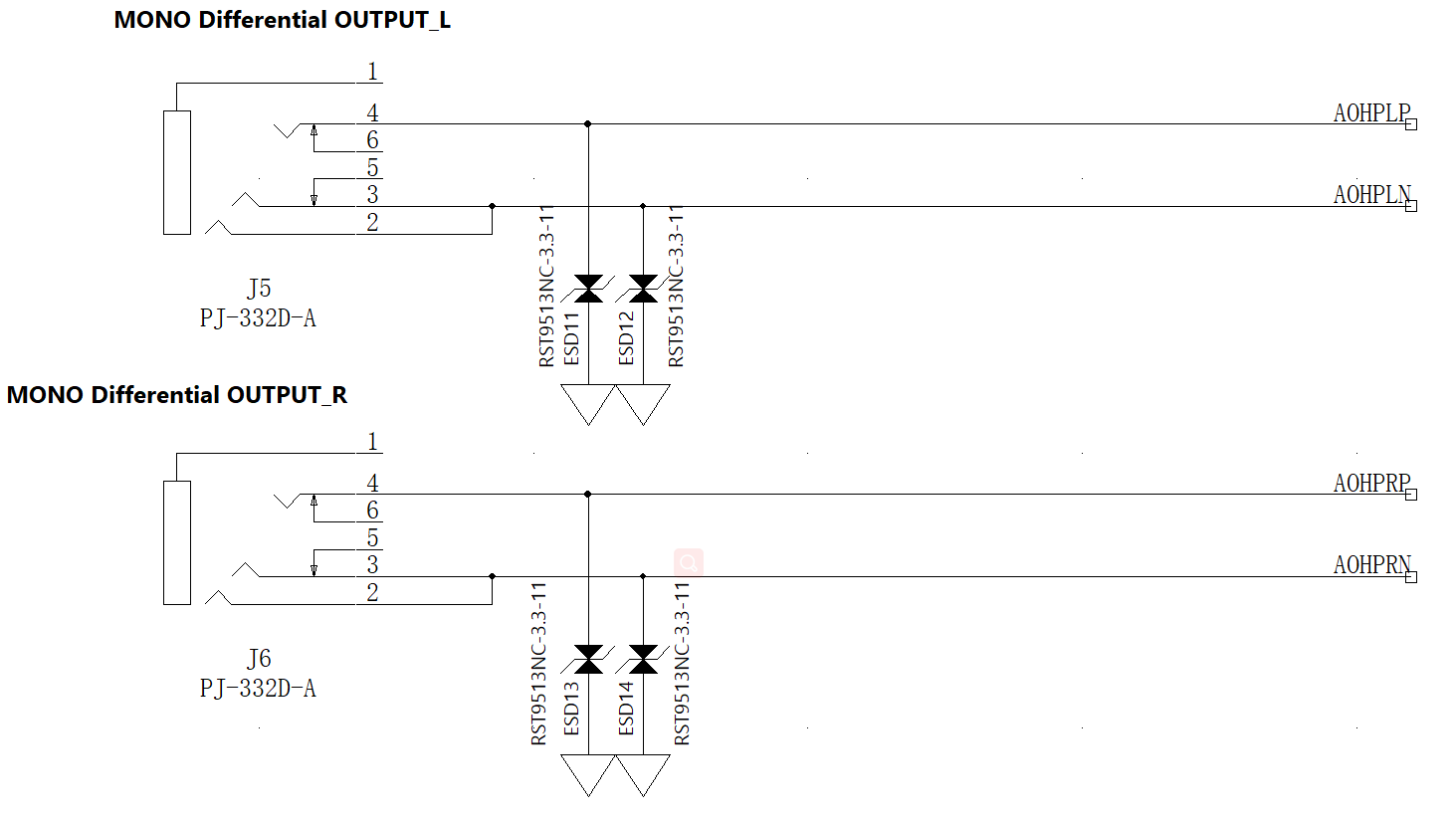
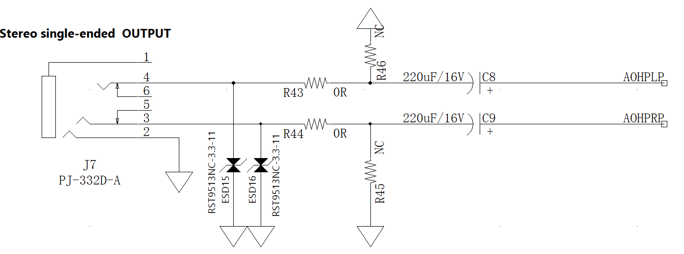
# Analog output
The evaluation board provides two types of analog outputs: a single-end stereo headphone interface and a dual differential interface.
In headphone output mode, the typical load is 16 Ω (60mW) to 32 Ω (30mW). By default, the load on Soundec Playground is 32 Ω.
Note:
- The analog output can also be connected to the output of adapter board through the P3. When the audio output is connected to adapter board, the audio output port on the evaluation board cannot be used.
# Digtial Microphone
There are up to 10 DMIC input ports on Soundec Playground. It can be connected to the microphone array adapter board through P3. DMIC is input through the interface on the adapter board.
| Pin | Pin Number |
|---|---|
| VDDIP33 | P3-15 |
| DMIC Clock1 | P3-26 |
| DMIC Data1 and DMIC Data2 | P3-25 |
| DMIC Clock2 | P3-28 |
| DMIC Data3 and DMIC Data4 | P3-27 |
| DMIC Clock3 | P3-30 |
| DMIC Data5 and DMIC Data6 | P3-29 |
| DMIC Clock4 | P3-33 |
| DMIC Data7 and DMIC Data8 | P3-31 |
| DMIC Clock8 | P3-34 |
| DMIC Data9 and DMIC Data10 | P3-32 |
# I2S
P2 and P3 can connect to I2S audio streams and support TDM format. The IOVDD logic level is 3.3 V.
| Pin | Pin Number |
|---|---|
| I2S1 Data Out | P2-2 |
| I2S1 Data In | P2-4 |
| I2S1 Frame Clock | P2-6 |
| I2S1 Bit Clock | P2-8 |
| MP0 | P2-10 |
| I2S2 Data Out | P3-2 |
| I2S2 Data In | P3-4 |
| I2S2 Frame Clock | P3-6 |
| I2S2 Bit Clock | P3-8 |
| External MCLK Input | P3-10 |
# Other Interfaces
# JTAG
There is a JTAG port pin in P2, which supports communication with Tensilia HiFi 3 DSP through J-Link for debugging and tracking.
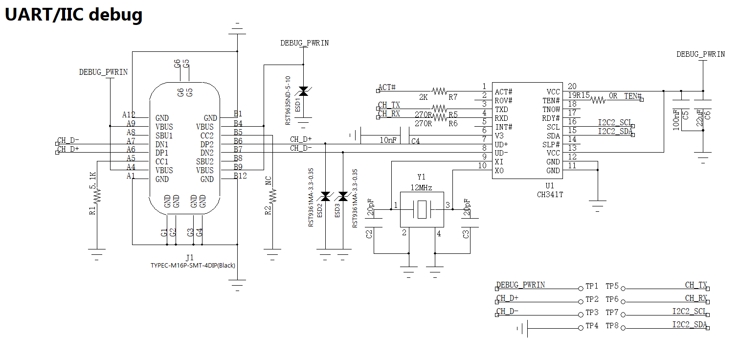
# UART
J1 is a USB-C female interface that supports UART protocol and evaluation board interaction.
# Hardware Description
# Ports
The following table lists the connection port functions of the evaluation board:
| Name | Function | Description |
|---|---|---|
| P1 | POWER_5V connection | connect USB 5V to core board; current monitoring |
| P2 | JTAG interface | JTAG connection |
| P3 | Adaptor Board Interface | Connect to adapator board |
| P4 | IP33 output | IP33 output |
| P5 | IO33 output | IO33 output |
| P6 | RESET selection | RESET pull-up and pull-down selection |
| P7 | Wake up selection | Always_ON pull-up and pull-down selection |
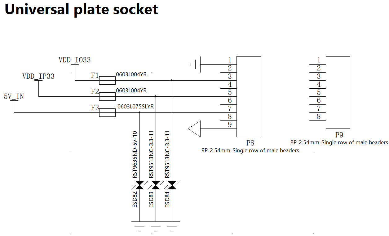
| P8 | Universal Board Interface | Connect to universal board |
| P9 | Universal Board Fix | Fix universal board |
| P10 | MICBIAS1 selection | provide bias to ADC1 when connect to ECM |
| P11 | MICBIAS2 selection | provide bias to ADC2 when connect to ECM |
| P12 | ADC1 single-end selection | AIN1 connect to ground for ADC1 single-end input |
| P13 | ADC2 single-end selection | AIN2 connect to ground for ADC2 single-end input |
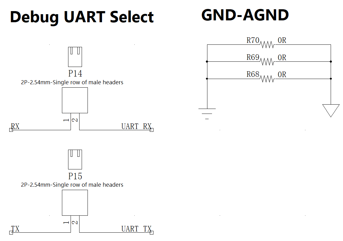
| P14 | RX disconnect | Disconnect RX with adptor board |
| P15 | TX disconnect | Disconnect TX with adptor board |
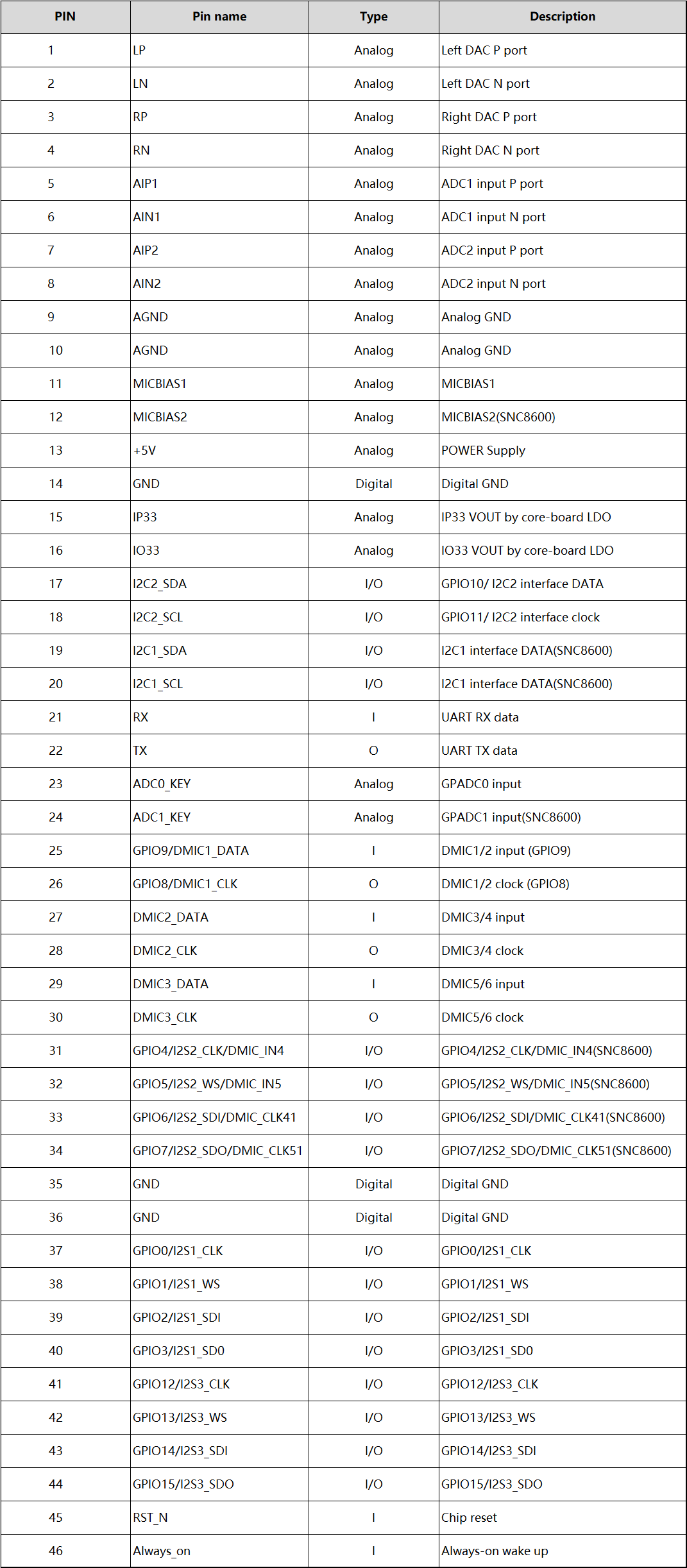
The following table lists the pin definitions for the P3 application module interface:
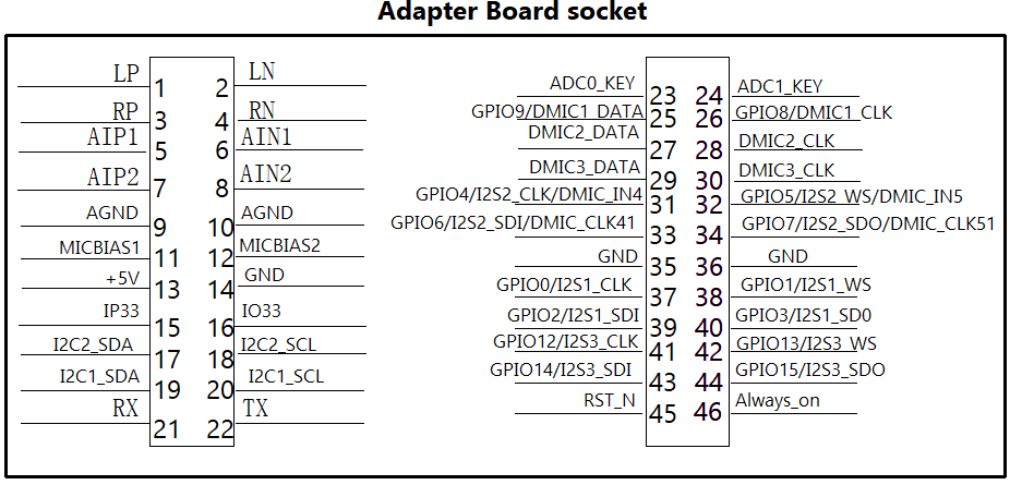
The following figure is a schematic diagram of P3 pins:
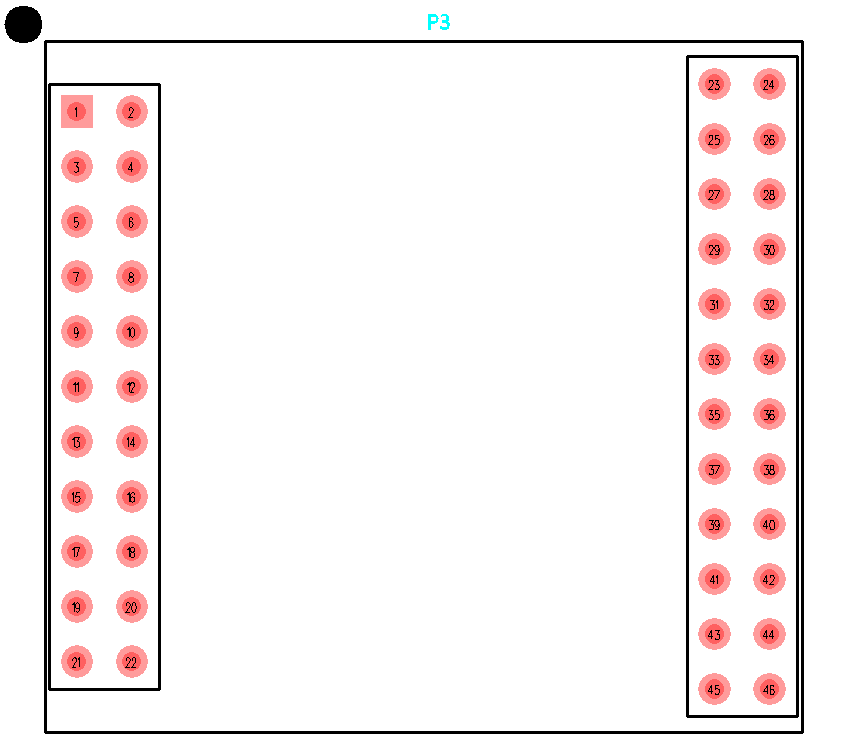
The following figure shows the pin layout of P3:
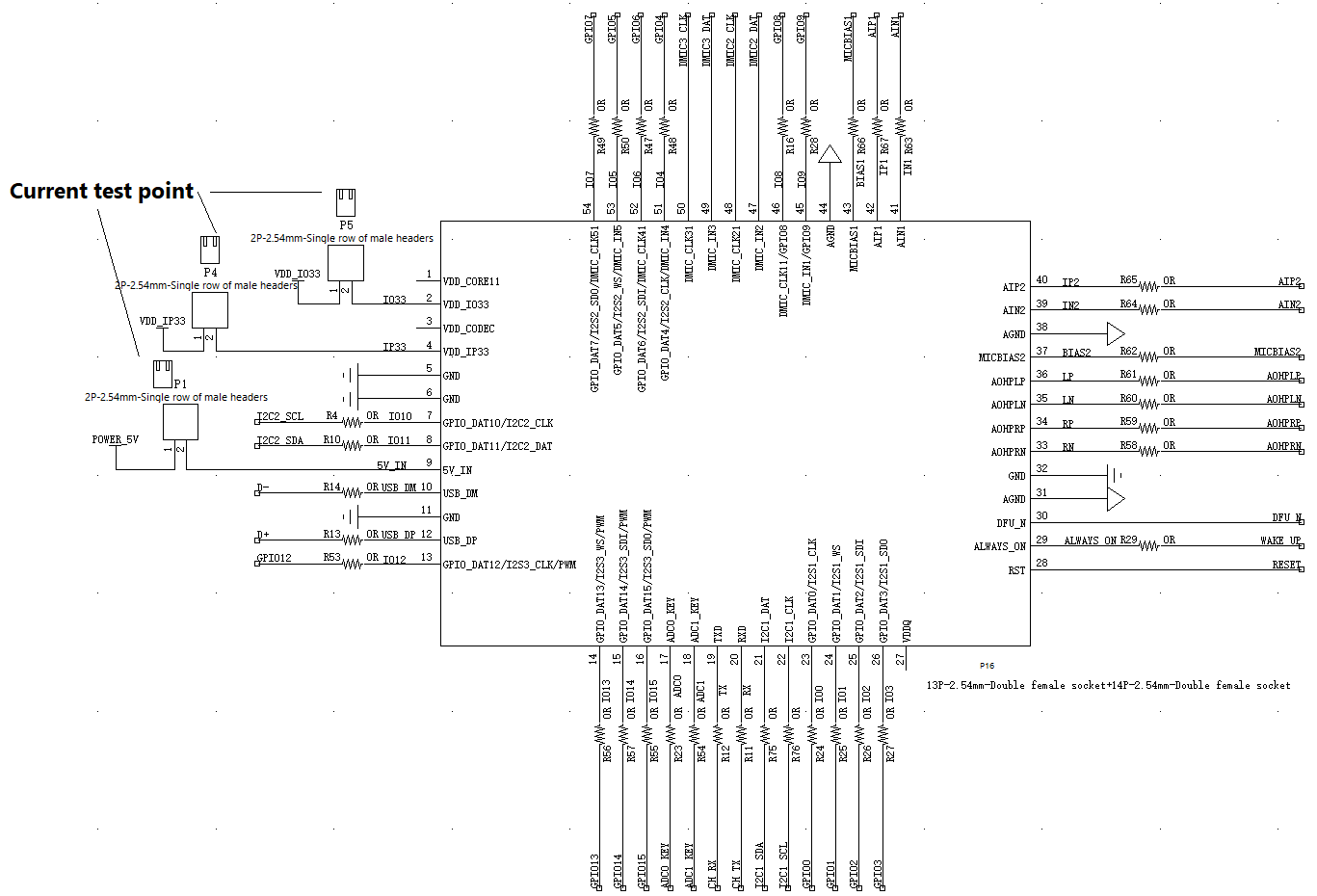
# Evaluation Board Schematics
Part 1:
Part 2:
Part 3:
Part 4:

Part 5:
Part 6:
Part 7:
Part 8:
Part 9:
Part 10:
Part 11:
Part 12:
Part 13:
Part 14:

Part 15:
Part 16:
Signal Diagram:
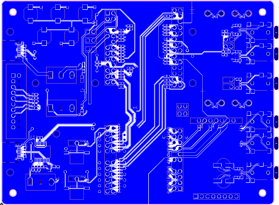
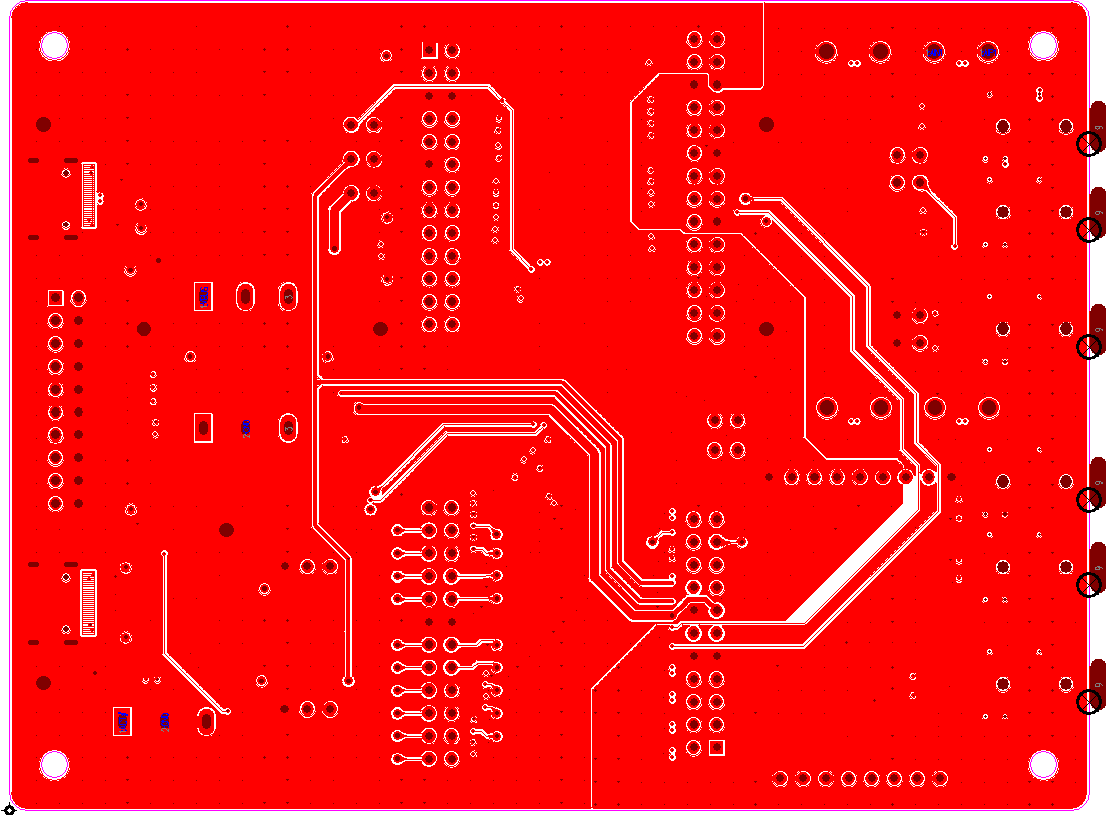
Layer 1, Component Side:
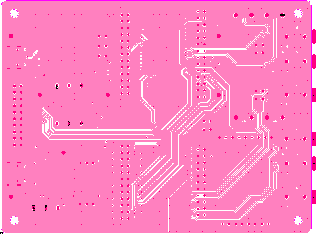
Layer 2, signal Plane:
Layer 3, signal Plane:
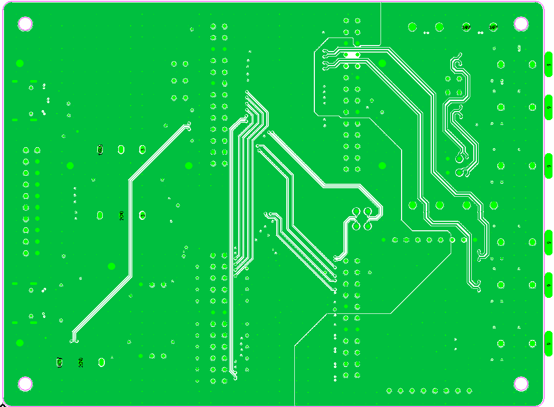
Layer 4, Bottom Side:
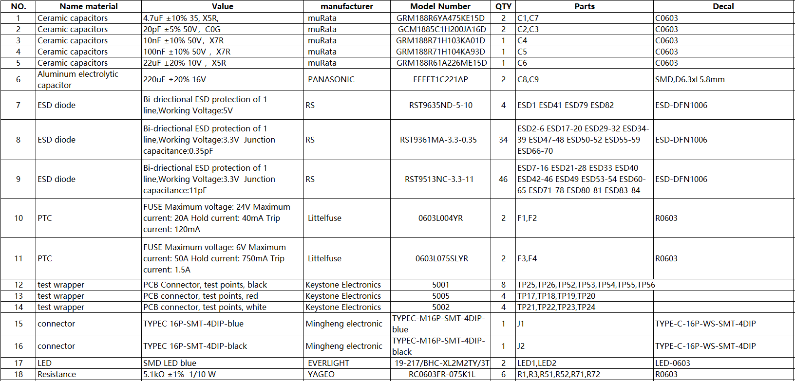
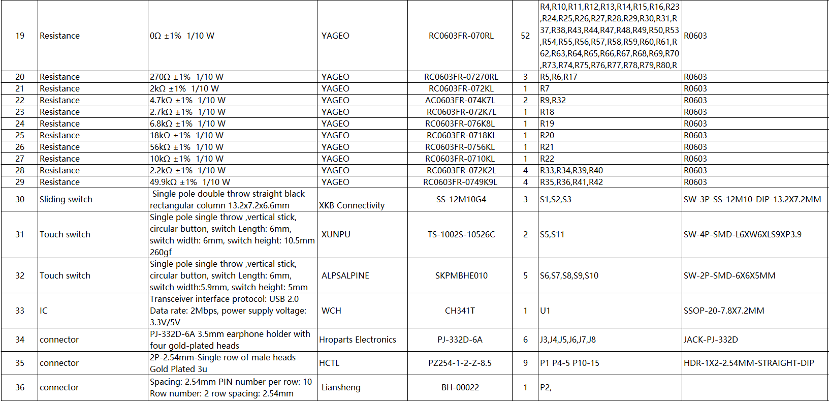
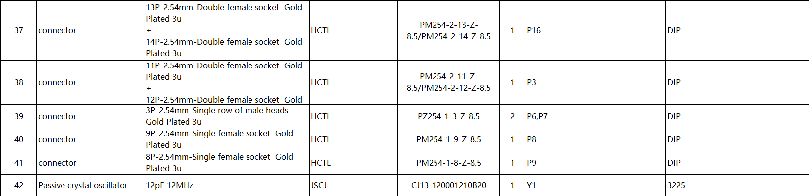
# BOM
The following is BOM list for the evaluation board: